Centrifugal shaper
A molding machine and rotating base technology, applied in ceramic molding machines, auxiliary molding equipment, manufacturing tools, etc., can solve the problems of affecting the working environment, liquid splashing, and complicated use process, avoiding relative sliding, increasing product types, and improving The effect of connection tightness
- Summary
- Abstract
- Description
- Claims
- Application Information
AI Technical Summary
Problems solved by technology
Method used
Image

Examples
Embodiment 1
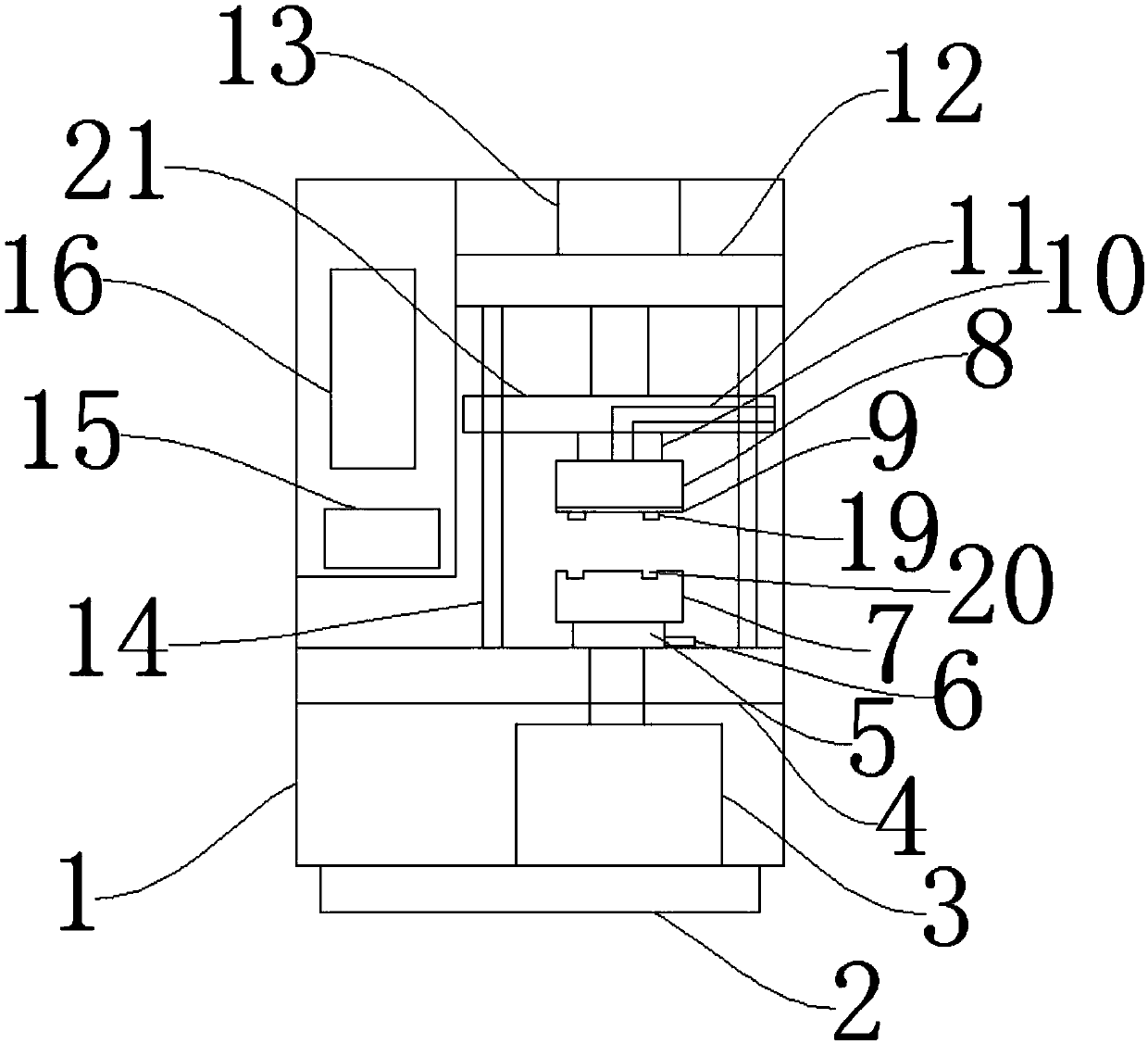
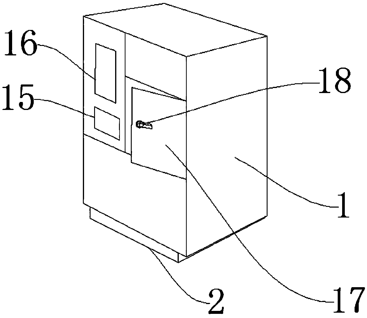
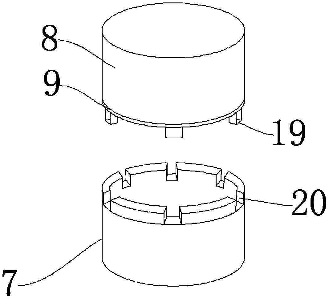
[0033] Such as Figure 1-Figure 3 As shown, a centrifugal molding machine includes a cabinet body 1, an upper rotating base 10, a lower rotating base 5, and a motor 3. A vibration damping seat 2 is arranged under the cabinet body 1 to reduce the impact of vibration during the molding process. The cabinet body 1 A motor 3 is arranged inside to provide power. A lower fixed plate 4 is arranged above the motor 3. A lower rotating base 5 is arranged above the lower fixed plate 4 to facilitate the installation of a lower mold 7. A lower mold 7 is arranged above the lower rotating base 5. The lower mold 7 is provided with a connection groove 20, correspondingly connected with the connection protrusion 19, an upper mold 8 is arranged above the lower mold 7, a connection protrusion 19 is arranged on the upper mold 8, and a sealing layer 9 is arranged above the connection protrusion 19 to improve sealing The upper mold 8 is provided with an upper rotating base 10, which is convenient fo...
Embodiment 2
[0035] The difference between this embodiment and embodiment 1 is:
[0036] The vibration damping seat 2 is connected with the cabinet body 1 through bolts, the motor 3 is connected with the cabinet body 1 through bolts, and the lower fixing plate 4 is connected with the cabinet body 1 through welding. The connection is stable, ensuring that the vibration damping seat 2 can stably support the cabinet body 1, and at the same time has a good vibration reduction effect, which helps the motor 3 to be firmly connected in the cabinet body 1, which is easy to disassemble and install. The welding connection helps to improve the lower fixing The connection strength between the board 4 and the cabinet body 1 improves usability.
Embodiment 3
[0038] The difference between this embodiment and embodiment 2 is:
[0039] The lower rotating base 5 is connected with the lower fixing plate 4 through bolts, and a liquid outlet pipe 6 is arranged on one side of the lower rotating base 5, and the lower rotating base 5 is connected with the liquid outlet pipe 6 through bolts, and the lower mold 7 is connected with the lower rotating base through bolts. 5 phase connection, the bolt connection helps the stable connection between the lower rotating base 5 and the lower fixing plate 4, helps the connection between the liquid outlet pipe 6 and the lower rotating base 5 to be firm, and is convenient for disassembly and installation.
[0040]Working principle: through the operation panel 15, relevant instruction operations can be carried out, and the hydraulic cylinder 13 is opened to drive the movable plate 21 to move down, and the upper mold 8 moves down at the same time, when the connecting protrusion 19 on the upper mold 8 and th...
PUM
 Abstract
Description
Claims
Application Information
 - R&D
- Intellectual Property
- Life Sciences
- Materials
- Tech Scout
- Unparalleled Data Quality
- Higher Quality Content
- 60% Fewer Hallucinations
Browse by: Latest US Patents, China's latest patents, Technical Efficacy Thesaurus, Application Domain, Technology Topic, Popular Technical Reports.
© 2025 PatSnap. All rights reserved.Legal|Privacy policy|Modern Slavery Act Transparency Statement|Sitemap|About US| Contact US: help@patsnap.com