
Drilling device and automatic plate feeding and discharging drilling system

A technology of drilling equipment and drilling mechanism, which is applied in the direction of drilling/drilling equipment, boring/drilling, metal processing equipment, etc., which can solve the problems of large safety hazards and low work efficiency, and achieve the goal of improving safety Effect

Pending Publication Date: 2020-03-03
SUZHOU VEGA TECH CO LTD
View PDF0 Cites 1 Cited by
  • Summary
  • Abstract
  • Description
  • Claims
  • Application Information

AI Technical Summary

Problems solved by technology

[0006] The purpose of the present invention is to provide a drilling equipment to alleviate the technical problems of large potential safety hazards and low work efficiency caused by the overlapping of the active area of ​​the operator and the active area of ​​the upper and lower plate equipment when maintaining the spindle

Method used


Image

  • Drilling device and automatic plate feeding and discharging drilling system
  • Drilling device and automatic plate feeding and discharging drilling system
  • Drilling device and automatic plate feeding and discharging drilling system

Examples


Embodiment 1

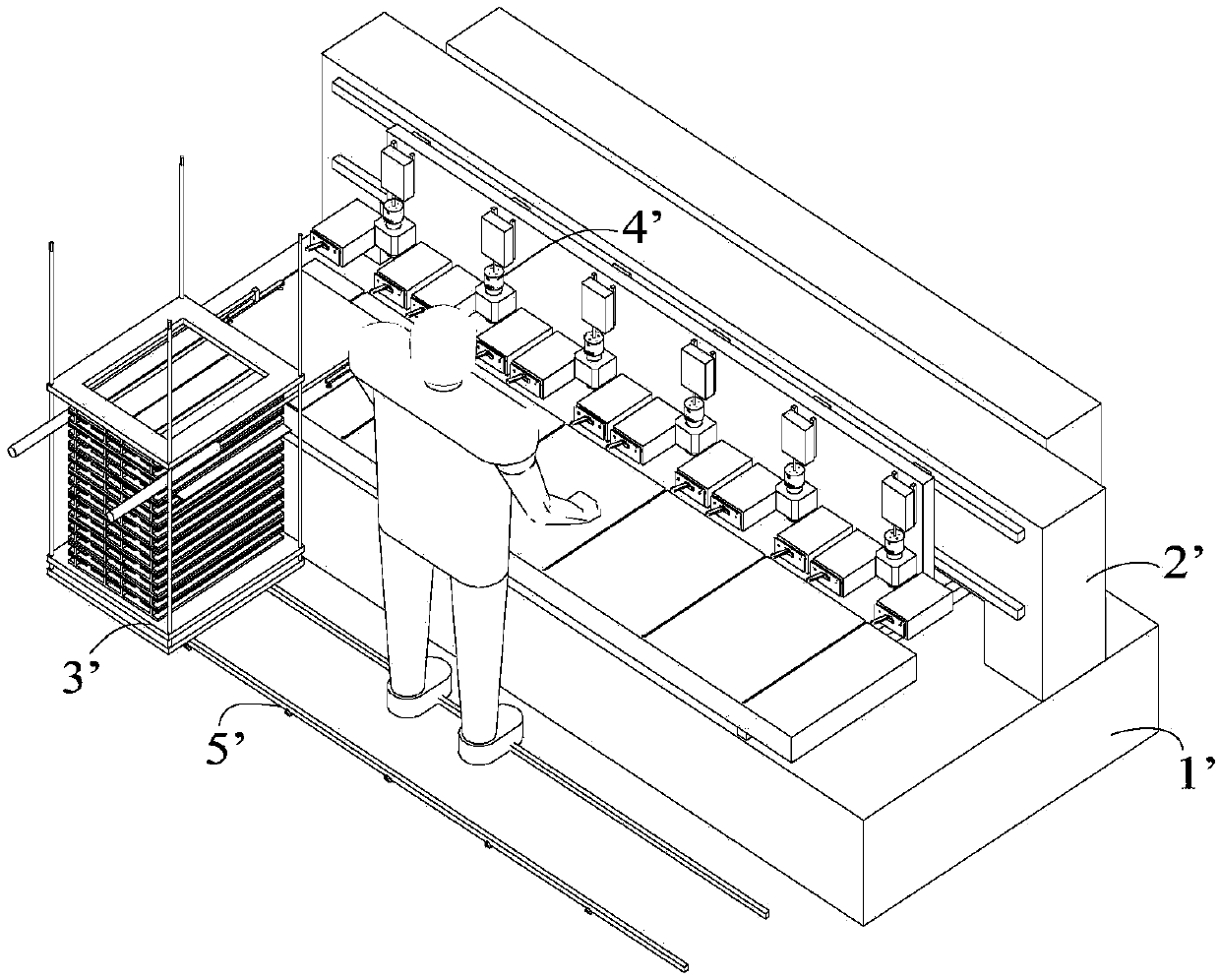
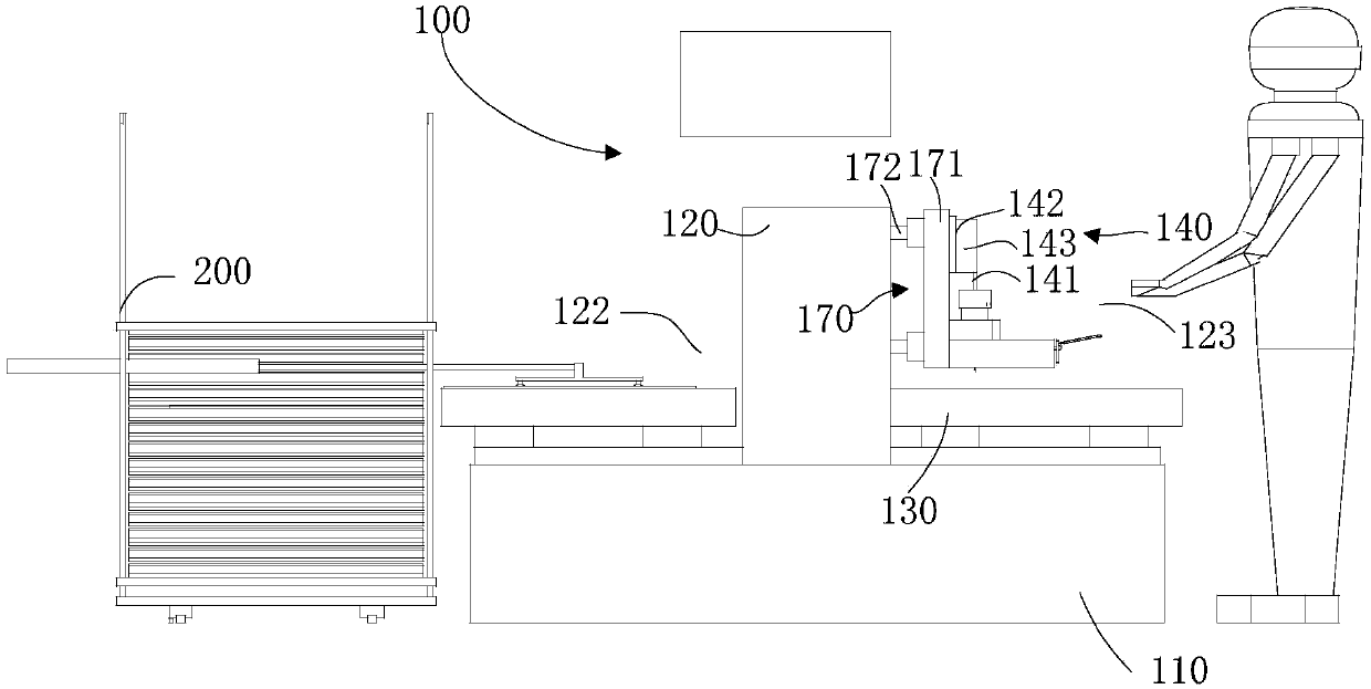
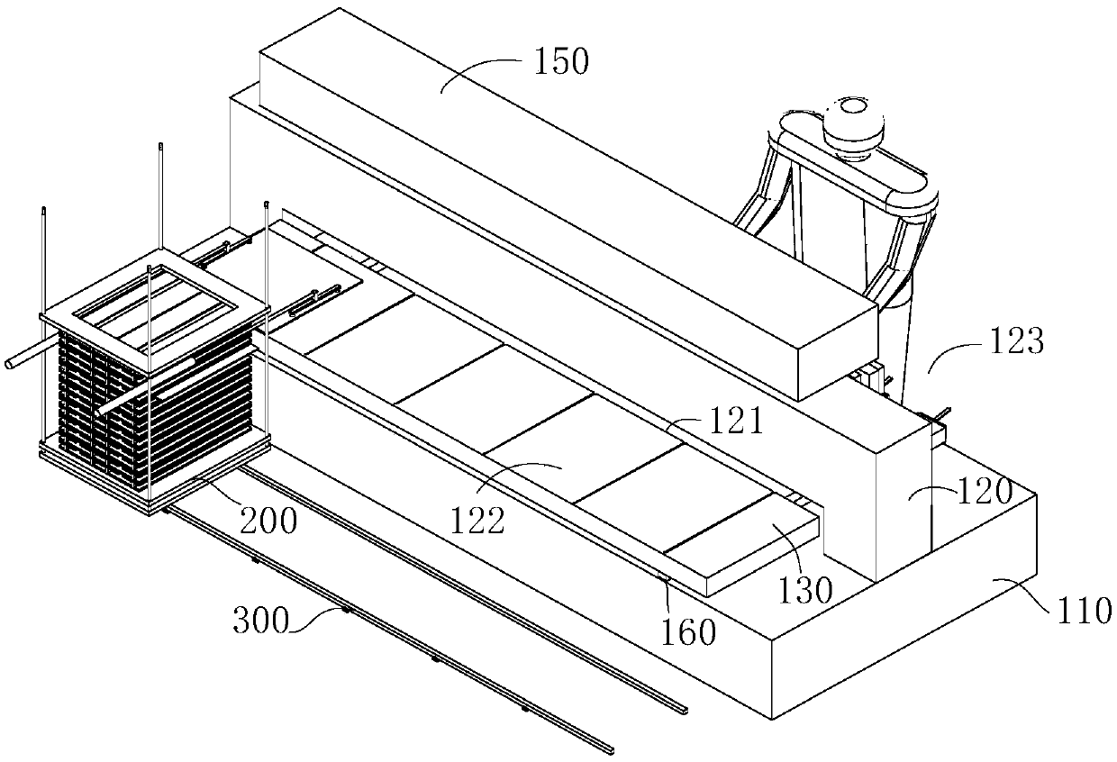
[0046] This embodiment provides a kind of drilling equipment, please refer to Figure 1 to Figure 4 , figure 1 It is a structural schematic diagram of the automatic upper and lower plate drilling system in the prior art; figure 2 The right view of the automatic upper and lower plate drilling system provided by the embodiment of the present invention; image 3 A schematic structural diagram of the first station in the automatic upper and lower plate drilling system provided by the embodiment of the present invention; Figure 4 It is a schematic structural diagram of the second station in the automatic upper and lower plate drilling system provided by the embodiment of the present invention.

[0047] Including: bed 110, crossbeam 120, workbench 130 and drilling mechanism 140; crossbeam 120 is located on the upper part of bed 110 and has channel 121 between bed 110, the two sides of crossbeam 120 form the first station 122 and the second Station 123, the first station 122 is ...


PUM


Abstract

The invention relates to the technical field of machining, in particular to a drilling device and an automatic plate feeding and discharging drilling system in order to alleviate the technical problems that as the activity area of an operator overlaps the activity area of a plate feeding and discharging device when a main shaft is maintained, high safety risks exist and the working efficiency is low. The drilling device comprises a body, a beam, a working table and a drilling mechanism; the beam is located on the upper portion of the body, a channel is formed between the beam and the body, a first station and a second station are formed on the two sides of the beam, the first station is used for feeding, and the drilling mechanism is installed at the second station; and the working table can pass through the channel to enter the second station from the first station, or pass through the channel to enter the first station from the second station. When the main shaft of the drilling mechanism is maintained, the operator stands at the second station, the activity area of the operator does not overlap the activity area of the automatic loading and unloading device, the automatic loading and unloading device does not need to avoid the operator, safety accidents are avoided, the operator can conveniently act freely, and the efficiency can be easily improved.

Description

technical field [0001] The invention relates to the technical field of mechanical processing, in particular to a drilling device and an automatic upper and lower plate drilling system. Background technique [0002] With the rise of manufacturing costs and the safety requirements in the production process, industrial robots with high efficiency and labor saving are more and more favored by factory workers, and the application range of industrial robots is gradually expanding. [0003] The application of industrial robots in drilling equipment has gradually replaced human operations. The prior art provides a drilling system whose structure is as follows: figure 1 As shown, considering the cost and the problem of occupying workshop space, the drilling system in the present technology includes a bed 1', a beam 2', an automatic upper and lower plate equipment 3' and a drilling mechanism 4'. The beam 2' is located on the upper part of the bed 1', the drilling mechanism 4' is inst...

Claims


Application Information

Patent Timeline
IPC IPC(8): B23B39/16B23Q1/01
CPCB23B39/161B23Q1/015B23Q1/017
Inventor 沈海涛庞士君常远邱四军
Owner SUZHOU VEGA TECH CO LTD
Learn More