Efficient heat dissipation type permanent magnet motor shell

A permanent magnet motor, heat dissipation technology, applied in the direction of the casing/cover/support, electrical components, electromechanical devices, etc., can solve the problems of motor burnout, motor heat accumulation, and inability to dissipate motor heat.

Pending Publication Date: 2020-02-28
JIANGSU SHILONG MOTOR
View PDF0 Cites 1 Cited by
  • Summary
  • Abstract
  • Description
  • Claims
  • Application Information

AI Technical Summary

Problems solved by technology

[0005] The purpose of the present invention is to provide a high-efficiency heat-dissipating permanent magnet motor casing, through which the hot air flow inside the motor can be circulated through the ventilation chamber and sent into the heat-dissipating box through the air-collecting pipe, the heat-dissipating box and the fan, and the heat-dissipating box can dissipate heat from the hot air Cooling, the heat dissipation fins can play the role of auxiliary heat dissipation, which solves the problem that the existing motor shell cannot dissipate the heat generated by the motor in a timely and rapid manner, resulting in heat accumulation inside the motor and easily causing the motor to burn out

Method used


Image

  • Efficient heat dissipation type permanent magnet motor shell
  • Efficient heat dissipation type permanent magnet motor shell
  • Efficient heat dissipation type permanent magnet motor shell

Examples


Embodiment Construction

[0024] The technical solutions in the embodiments of the present invention will be clearly and completely described below with reference to the accompanying drawings in the embodiments of the present invention. Obviously, the described embodiments are only a part of the embodiments of the present invention, but not all of the embodiments. Based on the embodiments of the present invention, all other embodiments obtained by those of ordinary skill in the art without creative efforts shall fall within the protection scope of the present invention.

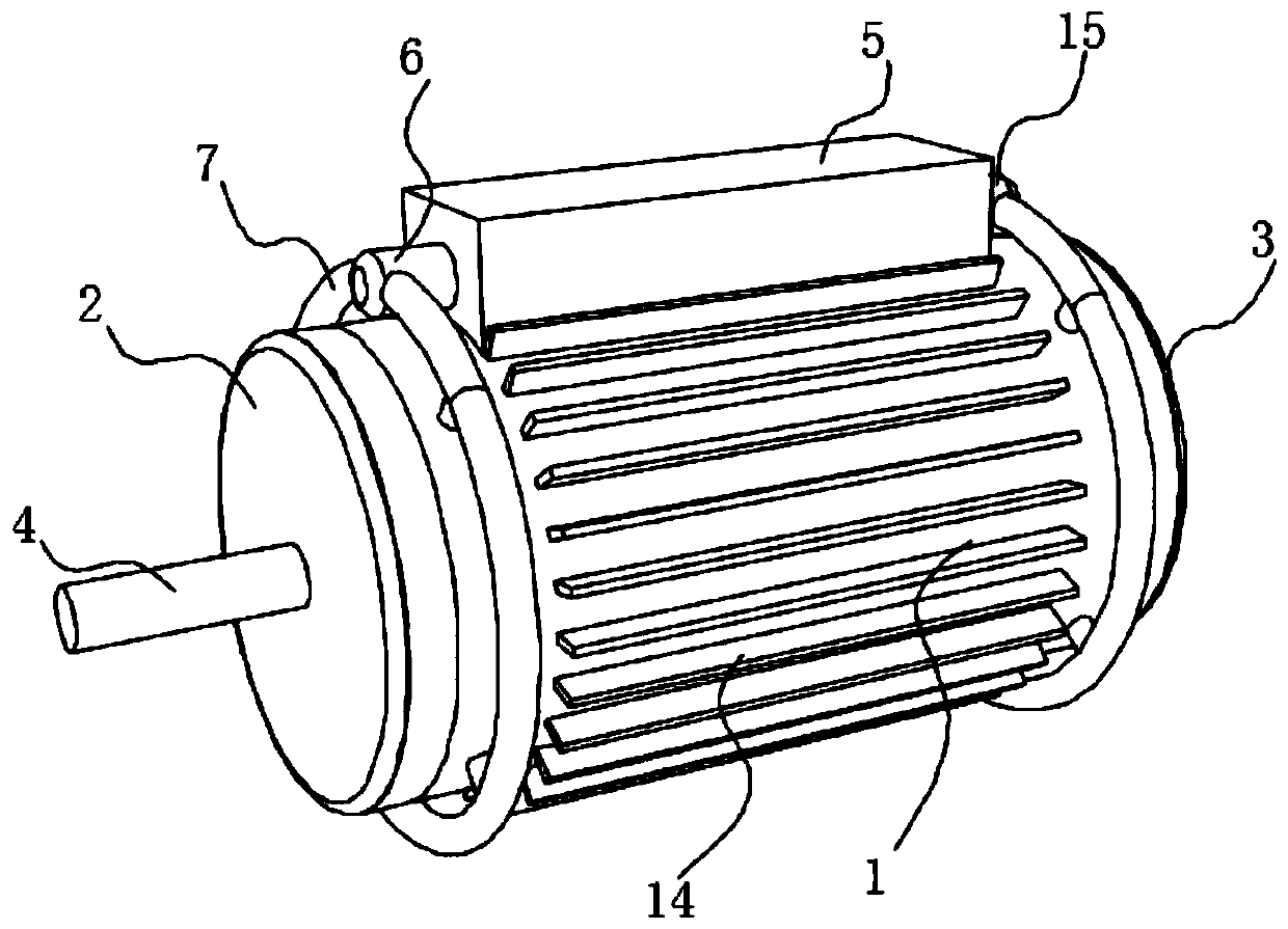
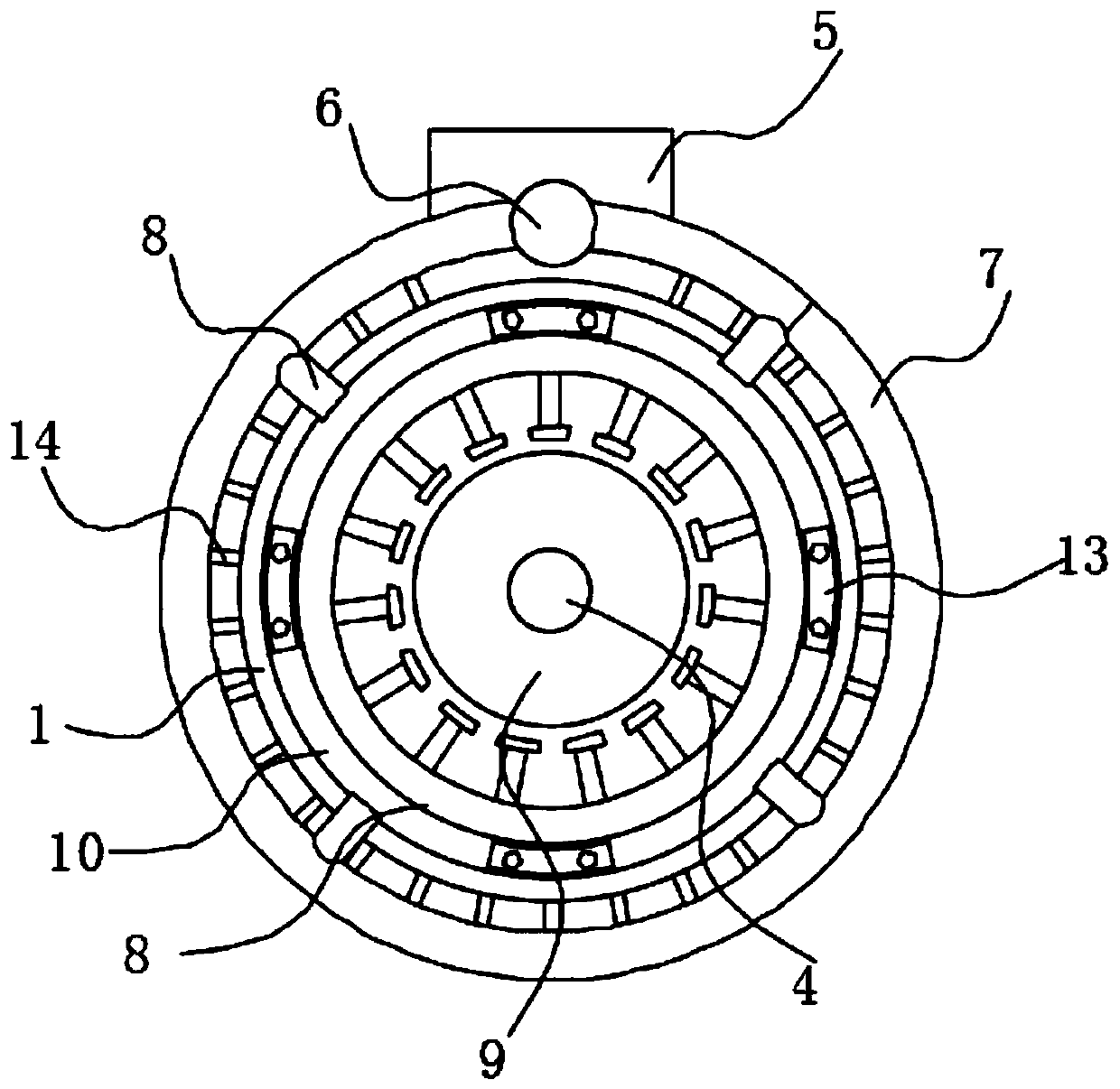
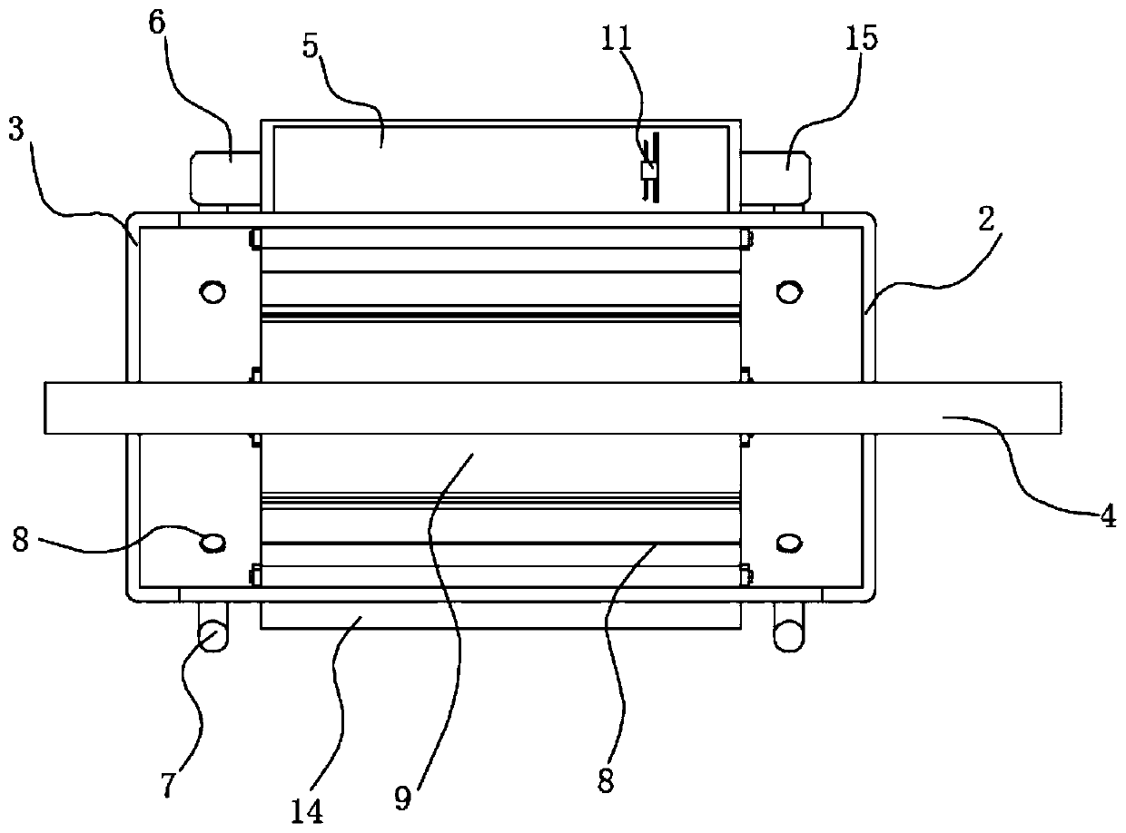
[0025] see Figure 1-4 As shown, the present invention is a high-efficiency heat dissipation permanent magnet motor casing, including an outer casing 1 and a fan 11, a rotor 9 and a stator core 16 are arranged inside the outer casing 1, and a rotating shaft 4 is arranged inside the rotor 9;

[0026] Both sides of the outer casing 1 are respectively fixed with a front end cover 2 and an inner end cover 3, the peripheral side of the out...


PUM


Abstract

The invention discloses an efficient heat dissipation type permanent magnet motor shell, and relates to the technical field of motors. The efficient heat dissipation type permanent magnet motor shellcomprises a shell body and a fan. A front end cover and an inner end cover are fixedly connected to the two sides of the shell body respectively. A plurality of radiating fins are fixedly connected tothe peripheral side surface of the shell body in a fan shape. A heat dissipation box is fixedly connected to the top of the shell body. An air outlet pipe and an air inlet pipe are respectively fixedto the two ends of the heat dissipation box in a penetrating mode. Air collection pipes are respectively fixed to one end of the air outlet pipe and to one end of the air inlet pipe in a penetratingmode. A plurality of ventilation pipes are fixedly communicated with the inner sides of the air collection pipes. One end of each ventilation pipe is fixedly communicated with the shell body. The fanis fixedly installed in the heat dissipation box through a bracket. Hot airflow in the motor can be circularly fed into the heat dissipation box via a ventilation cavity through the air collection pipes, the heat dissipation box and the fan, the heat dissipation box cools the hot airflow, and the radiating fins can play a role in auxiliary heat dissipation.

Description

technical field [0001] The invention belongs to the technical field of motors, and in particular relates to a permanent magnet motor casing. Background technique [0002] Motor refers to an electromagnetic device that realizes the conversion or transfer of electric energy according to the law of electromagnetic induction. The motor is represented by the letter M (the old standard is D) in the circuit. Its main function is to generate driving torque, as an electrical appliance or various The mechanical power source, the generator is represented by the letter G in the circuit, and its main function is to convert mechanical energy into electrical energy. [0003] Permanent magnet motors are widely used in modern industry, agriculture and even commercial fields. With the advancement of technology, the motors are constantly updated. However, the current permanent magnet motors still have the problem of poor heat dissipation. The existing permanent magnet motors generally Mainly ...

Claims


Application Information

Patent Timeline
Patent Type & Authority Applications(China)
IPC IPC(8): H02K9/10H02K5/18H02K5/20
CPCH02K9/10H02K5/18H02K5/20
Inventor 丁玉林陈前卜飞飞
Owner JIANGSU SHILONG MOTOR
Why Eureka
Try Eureka