
A zigbee smart socket with voice control function

A technology of voice control and smart socket, which is applied to the parts of the connection device, the coupling device, the two-part connection device, etc., which can solve the problems of inability to adjust the jack, inconvenient installation board, and inability to meet the needs of use, so as to avoid excessive heat dissipation. Slow, improve cooling effect, improve the effect of convenience

Active Publication Date: 2021-07-02
江苏企想科技有限公司
View PDF0 Cites 0 Cited by
  • Summary
  • Abstract
  • Description
  • Claims
  • Application Information

AI Technical Summary

Problems solved by technology

[0004] The purpose of the present invention is to provide a zigbee smart socket with voice control function to solve the problem of the existing smart socket mentioned in the above background technology. The problem of using requirements

Method used


Image

  • A zigbee smart socket with voice control function
  • A zigbee smart socket with voice control function
  • A zigbee smart socket with voice control function

Examples


Embodiment 1

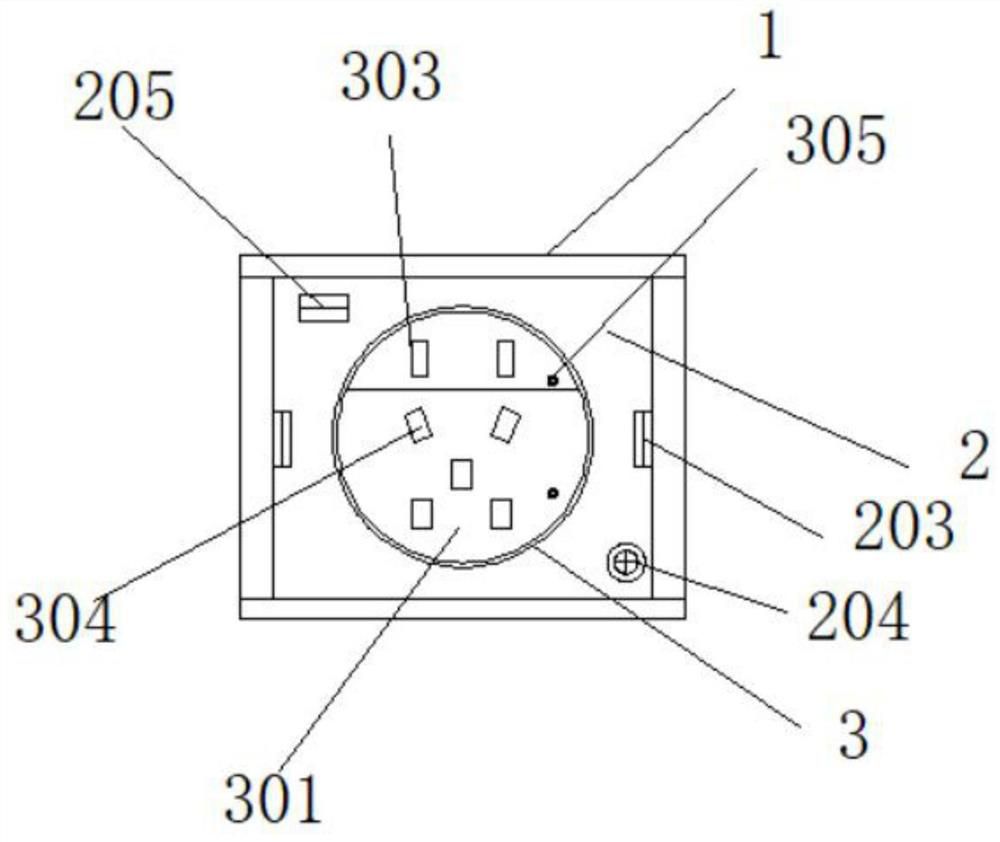
[0026] like Figure 1-6 As shown, the present invention provides a technical solution: a zigbee intelligent socket with a voice control function, including a mounting shell 1, a socket housing 2, a socket mounting groove 3, a power connection box 4, an electric control box 5 and The control module 6, the socket casing 2 is buckled and installed in the installation shell 1, the plug plate installation groove 3 is opened on the top surface of the socket casing 2, and the power connection box 4 bolts are installed inside the socket casing 2 , the electric control box 5 and the control module 6 are installed in the electric connection box 4 by bolts.

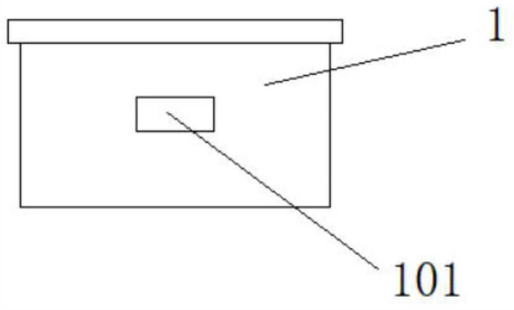
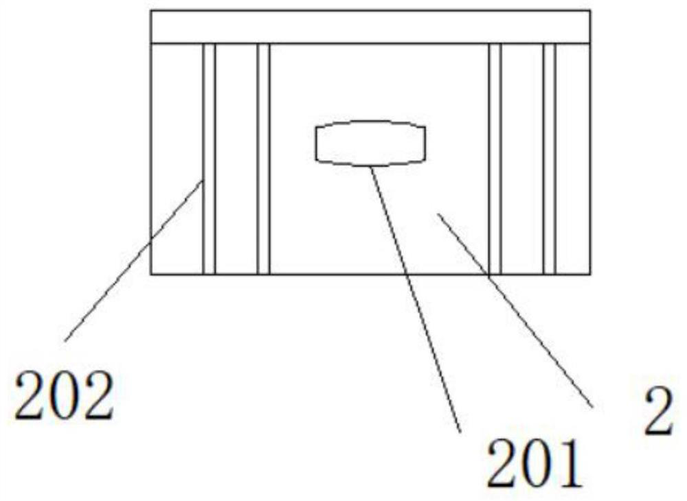
[0027] The inner wall of the installation shell 1 is provided with a buckle groove 101, and the surface of the socket housing 2 is provided with a buckle protrusion 201, and the buckle protrusion 201 is buckled in the buckle groove 101, and passes through the socket housing 2. The buckle protrusion 201 inlaid on the surface is conv...

Embodiment 2

[0036] like Figure 1-6 As shown, the present invention provides a technical solution: a zigbee intelligent socket with a voice control function, including a mounting shell 1, a socket housing 2, a socket mounting groove 3, a power connection box 4, an electric control box 5 and The control module 6, the socket casing 2 is buckled and installed in the installation shell 1, the plug plate installation groove 3 is opened on the top surface of the socket casing 2, and the power connection box 4 bolts are installed inside the socket casing 2 , the electric control box 5 and the control module 6 are installed in the electric connection box 4 by bolts.

[0037] The inner wall of the installation shell 1 is provided with a buckle groove 101, and the surface of the socket housing 2 is provided with a buckle protrusion 201, and the buckle protrusion 201 is buckled in the buckle groove 101, and passes through the socket housing 2. The buckle protrusion 201 inlaid on the surface is conv...


PUM


Abstract

The invention discloses a zigbee intelligent socket with a voice control function, which includes a mounting shell, a socket casing, a socket mounting slot, an electrical connection box, an electric control box and a control module, and the socket casing buckle is installed on In the installation shell, the plugboard installation groove is opened on the top surface of the socket casing, the bolts of the power connection box are installed inside the socket casing, and the electric control box and the control module are both bolted in the power connection box. In the present invention, the buckle protrusion embedded on the surface of the socket casing is convenient to cooperate with the buckle groove opened on the inner wall of the installation shell to fix the socket casing, and at the same time, it is convenient to disassemble and maintain the socket casing. The dismantling groove provided makes it convenient to use the dismounting groove to pry up the corners of the socket casing and take out the socket casing from the installation casing, thereby improving the convenience of dismounting the socket casing.

Description

technical field [0001] The invention relates to the field of sockets, in particular to a zigbee intelligent socket with a voice control function. Background technique [0002] Generally speaking, smart socket is a kind of socket that saves electricity consumption. The concept of energy-saving socket has been generated a long time ago, and it has been developed widely so far, but the technology still needs to be improved. Some high-end energy-saving sockets not only save electricity, but also protect electrical appliances. They can be connected to handheld devices through Wifi, Bluetooth, etc. [0003] However, the existing smart socket has an inconvenient mounting plate, and the socket cannot be adjusted according to the usage requirements, so that the usage requirements cannot be met. Contents of the invention [0004] The purpose of the present invention is to provide a zigbee smart socket with voice control function to solve the problem of the existing smart socket men...

Claims


Application Information

Patent Timeline
Patent Type & Authority Patents(China)
IPC IPC(8): H01R13/74H01R13/512H01R13/502H01R24/76H01R27/00H01R13/648H01R13/66H01R13/70H01R13/717H01R35/00
CPCH01R13/502H01R13/512H01R13/648H01R13/66H01R13/665H01R13/6691H01R13/70H01R13/717H01R13/743H01R24/76H01R27/00H01R35/00
Inventor 金茂瑞王亮蒋慧陈彬
Owner 江苏企想科技有限公司
Learn More