Adjustable suspension formwork construction method without support at lower part

A construction method and an adjustable technology, applied in earth-moving drilling, mining equipment, mining equipment, etc., can solve the problem that the safety of the formwork support of the structural side wall and the construction quality of the structural side wall cannot be guaranteed, the main structure cannot meet the requirements of the node construction period, and the urban The problems such as the narrow space of the rail transit station have achieved the effect of avoiding the difficulty of construction organization, no potential safety hazards, and solving the tense construction period.

Active Publication Date: 2020-02-28
中铁隧道局集团建设有限公司
View PDF3 Cites 0 Cited by
  • Summary
  • Abstract
  • Description
  • Claims
  • Application Information

AI Technical Summary

Problems solved by technology

The construction of the rail top air duct needs to be erected again, but the site of the urban rail transit station is small, and under the premise of the cross construction of the shield machine, the construction of the rail top air duct support cannot be carried out simultaneously, thus affecting the construction period of important nodes of the entire urban rail transit station
[0003] If the rail top air duct and the main structure are constructed synchronously, the construction period of the main structure will be occupied, which will cause the main structure to fail to meet the node construction period requirements, and the distance between the rail top air duct wall and the side wall of the main structure of the station is only 50cm, and the simultaneous construction cannot guarantee the formwork support of the structural side wall Safety and Construction Quality of Structural Side Walls

Method used


Image

  • Adjustable suspension formwork construction method without support at lower part
  • Adjustable suspension formwork construction method without support at lower part
  • Adjustable suspension formwork construction method without support at lower part

Examples


Embodiment 1

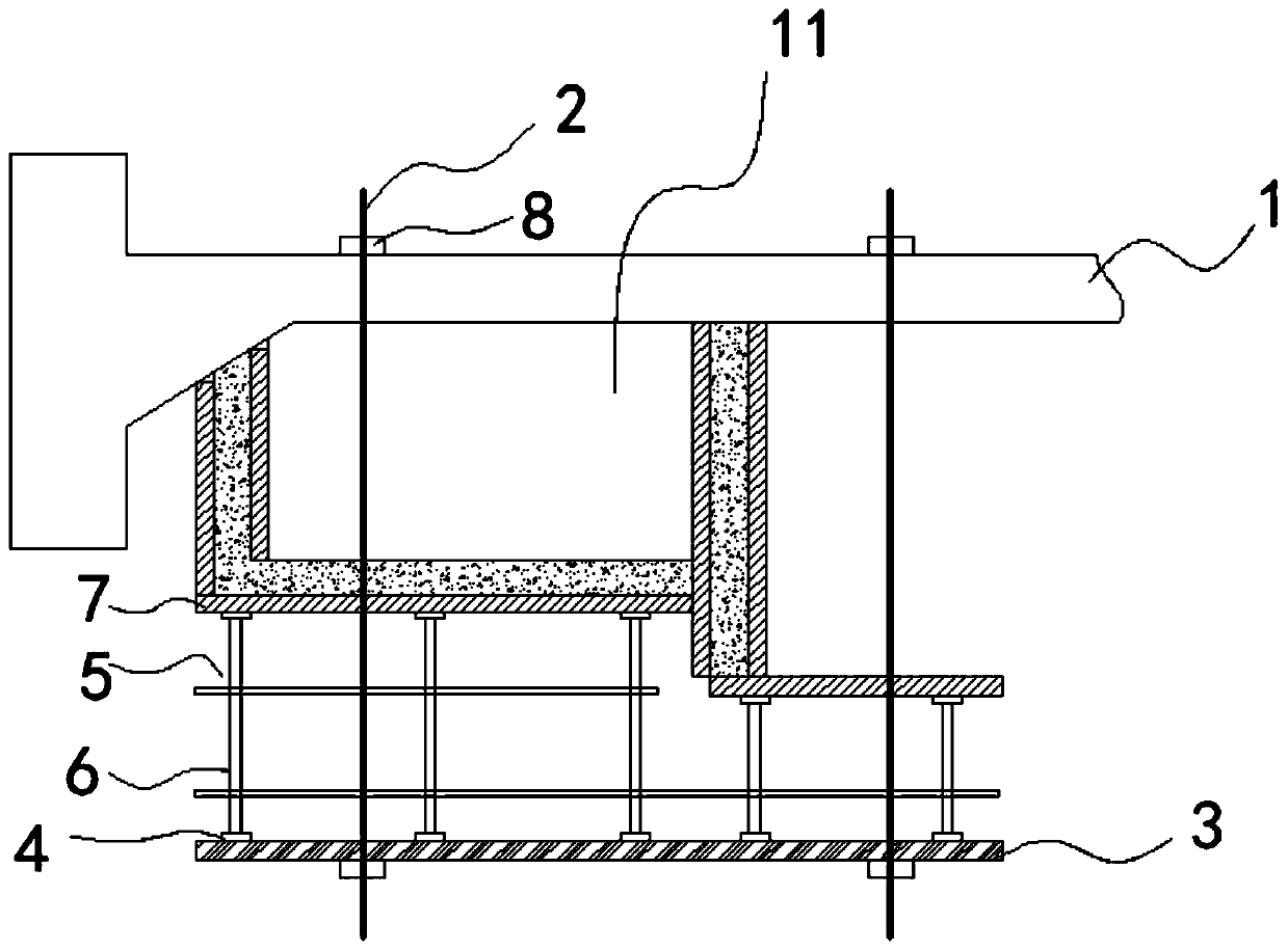
[0043] Such as Figure 1~3 As shown, a construction method of adjustable hanging formwork without support at the bottom is used for the construction of rail top air ducts in urban rail transit stations, including:

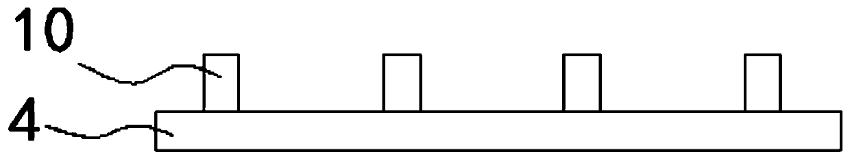
[0044] After a hole is opened on the middle plate 1 of the main structure of the station, a boom 2 is installed through the hole, a longitudinal beam 3 is hung on the boom 2, and a crossbeam 4 is built on the longitudinal beam 3 to form a support base;

[0045] Build the support 5 on the basis of the support, and then lay the main flute, the secondary flute and the formwork 7, thereby completing the hanging formwork construction.

[0046] Said suspenders 2 are provided with 2 lines horizontally and vertically at intervals of 2000 mm.

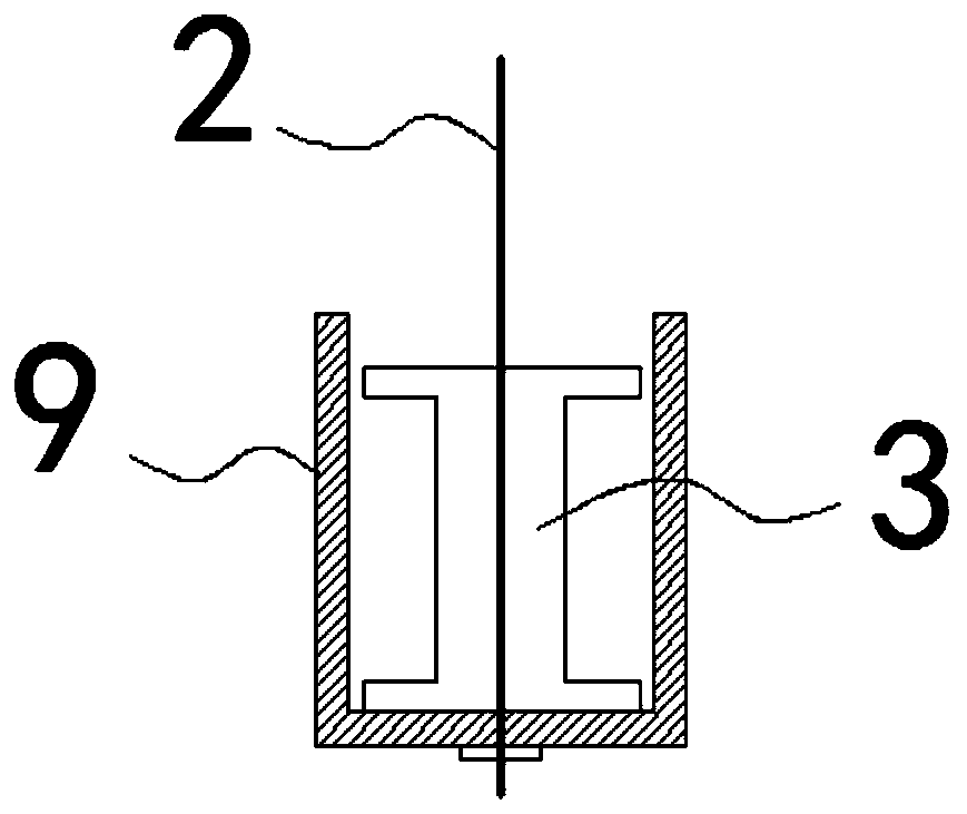
[0047] Specific as image 3 As shown, the lower end of the boom 2 is provided with a U-shaped bracket 9 , and the longitudinal beam 3 is lifted by the U-shaped bracket 9 .

[0048] The suspender 2 is a fine-rolled threaded steel ...

Embodiment 2

[0054] Such as Figure 1~4 As shown, a construction method of adjustable hanging formwork without support at the bottom is used for the construction of rail top air ducts in urban rail transit stations, including:

[0055] After a hole is opened on the middle plate 1 of the main structure of the station, a boom 2 is installed through the hole, a longitudinal beam 3 is hung on the boom 2, and a crossbeam 4 is built on the longitudinal beam 3 to form a support base;

[0056] Build the support 5 on the basis of the support, and then lay the main flute, the secondary flute and the formwork 7, thereby completing the hanging formwork construction.

[0057] Said suspenders 2 are provided with 2 lines horizontally and vertically at intervals of 2000 mm.

[0058] Specific as image 3 As shown, the lower end of the boom 2 is provided with a U-shaped bracket 9 , and the longitudinal beam 3 is lifted by the U-shaped bracket 9 .

[0059] The suspender 2 is a fine-rolled threaded steel ...

Embodiment 3

[0072] The technological process of the present invention: measuring and setting off → mechanical milling of the middle plate → installation of suspenders → installation of I-beams for longitudinal beams → installation of I-beams for crossbeams → erection of supports → laying of main corrugations, secondary corrugations and formwork.

[0073] Specifically: measure the center line of the Φ20 fine-rolled threaded suspender on the middle plate, arrange the row spacing at a vertical distance of 2m, mark the position of the hole, and then perform mechanical milling (the hole diameter is Φ32mm).

[0074] After the milling is completed, install the Φ20 fine-rolled thread suspenders and double-spelled 18# I-beam longitudinal beams, and install at least 2 U-shaped brackets under each double-spelled 18# I-steel longitudinal beams to connect with the suspenders ;Install the specification 100*100mm, t=10 steel pads on the top of the suspender (middle plate skin) and bottom (below the longi...


PUM


Abstract

The invention discloses an adjustable suspension formwork construction method without a support at the lower part. The method is used for track top air duct construction of an urban rail transit station. The method comprises the steps that after holes are formed in a middle plate of a station main body structure, suspenders are installed in a manner of penetrating through the holes, longitudinal beams are hung on the suspenders, and a cross beam is built on the longitudinal beams to form a support foundation; and the support is erected on the support foundation, and then a main ridge, a secondary ridge and a template are laid so as to finish the suspended formwork construction. According to the track top air duct suspension formwork construction method, the support does not need to be erected on the lower part, so that the occupied space is small, the method can synchronously work with a shield, the risks of low construction quality, construction period delay and project slowdown due to the construction organization difficulty and the technical difficulty are avoided, and the problems that during metro construction, the time limit is short, the processes are complex, and the station and the shield are subjected to cross construction are solved.

Description

technical field [0001] The invention relates to the technical field of tunnel construction. More specifically, the invention relates to a construction method of a bottom-less adjustable hanging formwork that can be used in the construction of post-cast structures such as rail top air ducts and plywood layers of subway stations. Background technique [0002] Affected by the construction period of the main structure and the drawing time of the construction drawings, the air ducts of the middle rails of urban rail transit stations usually need to be constructed in the later stage. The construction of the rail top air duct needs to be erected again, but the site of the urban rail transit station is small, and under the premise of the shield crossing construction, the construction of the rail top air duct support cannot be carried out simultaneously, thus affecting the construction period of important nodes of the entire urban rail transit station. [0003] If the rail top air du...

Claims


Application Information

Patent Timeline
Patent Type & Authority Applications(China)
IPC IPC(8): E21F17/02E21F1/04E21F17/00
CPCE21F1/04E21F17/00E21F17/02
Inventor 姜冲莫智彪常建峰陈钢张阳张攀攀金济勇邹磊黄卫华段胜利
Owner 中铁隧道局集团建设有限公司
Why Eureka
Try Eureka