Driving motor resolver zero debugging method and device

A technology for driving motors and debugging methods, which is applied in the direction of motor generator testing, engine testing, and measuring devices. It can solve problems such as high cost, low efficiency, and complicated procedures, and achieve the effect of simple operation and fast detection speed.

Pending Publication Date: 2020-11-24
DONGFENG AUTOMOBILE ELECTRONICS
View PDF6 Cites 1 Cited by
  • Summary
  • Abstract
  • Description
  • Claims
  • Application Information

AI Technical Summary

Problems solved by technology
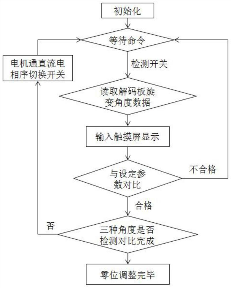
[0005] The embodiment of the present invention provides a method and device for debugging the zero position of the drive motor resolver, which solves the problems of complicated procedures, low efficiency, and high cost in the prior art when adjusting the zero point position angle of the drive motor in batches

Method used


Image

  • Driving motor resolver zero debugging method and device
  • Driving motor resolver zero debugging method and device
  • Driving motor resolver zero debugging method and device

Examples


Embodiment Construction

[0034] In order to make the purpose, technical solutions and advantages of the embodiments of the present invention clearer, the technical solutions in the embodiments of the present invention will be clearly and completely described below in conjunction with the drawings in the embodiments of the present invention. Obviously, the described embodiments It is a part of embodiments of the present invention, but not all embodiments. Based on the embodiments of the present invention, all other embodiments obtained by persons of ordinary skill in the art without creative efforts fall within the protection scope of the present invention.

[0035] The term "and / or" in the embodiment of the present application is only an association relationship describing associated objects, which means that there may be three relationships, for example, A and / or B, which can mean: A exists alone, and A and B exist at the same time , there are three cases of B alone.

[0036] The terms "first" and "...


PUM


Abstract

The embodiment of the invention provides a driving motor resolver zero position debugging method and device, and solves the problems of complex process, low efficiency, high cost and the like in the prior art during batch driving motor zero position angle adjustment. A PLC control system is designed autonomously, the current resolver angle is displayed in real time, manual adjustment is matched, the real-time angle value is made to be within the set angle range, then resolver is fixed, the motor zero point position requirement can be met, operation is easy and convenient, and the detection speed is high.

Description

technical field [0001] The embodiments of the present invention relate to the technical field of automatic control, and in particular to a method and device for debugging the zero position of a drive motor resolver. Background technique [0002] The driving motor is an important core component of the new energy vehicle. The accuracy of the rotor position angle information of the driving motor will directly affect the motor torque, the precision of the speed control and the dynamic performance. [0003] The position angle of the rotor of the drive motor cannot be directly measured. It can be judged by detecting the alternating signal output by the resolver (resolver for short) on the drive motor. The initial angle remains the same. Since the deviation value of the motor and the resolver cannot be determined during the manufacturing and assembly process, it is necessary to use a certain method to detect and adjust the angle of the resolver during the motor production and asse...

Claims


Application Information

Patent Timeline
Patent Type & Authority Applications(China)
IPC IPC(8): G01R31/34G01M15/00G01M15/02
CPCG01R31/34G01M15/02G01M15/00
Inventor 汪聪孙伟周厚泉
Owner DONGFENG AUTOMOBILE ELECTRONICS
Why Eureka
Try Eureka