
Construction method of continuous composite beam bridge and continuous composite beam bridge

A construction method and steel girder technology, applied to bridges, bridge parts, bridge materials, etc., can solve the problems of increasing the amount of wet work on site, affecting the bearing capacity of bridges, and poor concrete prestress, so as to reduce the amount of wet work on site and improve The effect of prestressing efficiency and reducing project cost

Pending Publication Date: 2020-02-28
湖南省交通水利建设集团有限公司
View PDF0 Cites 7 Cited by
  • Summary
  • Abstract
  • Description
  • Claims
  • Application Information

AI Technical Summary

Problems solved by technology

[0003] The purpose of the present invention is to solve the technical problems of poor concrete prestress in the negative bending moment area, easy cracking, weak compressive capacity and thus affecting the bearing capacity and durability of the bridge in the continuous composite girder bridge, and the increase of the site without the combination of the concrete bridge deck and steel girders. Technical issues with wet workloads

Method used


Image

  • Construction method of continuous composite beam bridge and continuous composite beam bridge
  • Construction method of continuous composite beam bridge and continuous composite beam bridge
  • Construction method of continuous composite beam bridge and continuous composite beam bridge

Examples


Embodiment 1

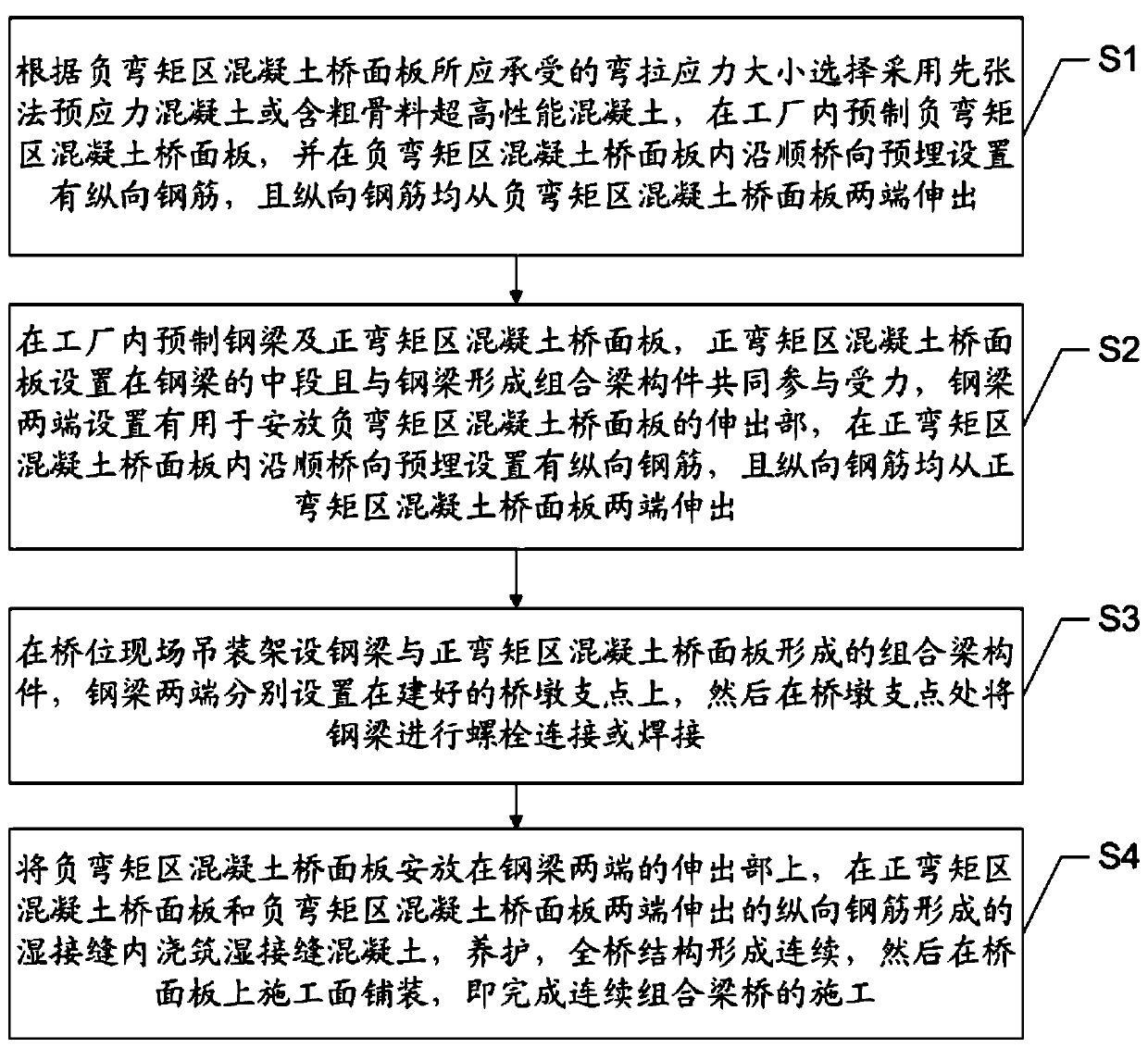
[0036] Such as figure 1 as shown, figure 1 It is a flow chart of a construction method for a continuous composite girder bridge provided in an embodiment of the present invention, comprising the following steps:

[0037] S1. Pre-tensioned prestressed concrete or ultra-high-performance concrete containing coarse aggregate is selected according to the bending and tensile stress of the concrete bridge deck in the negative bending moment area, and the concrete bridge deck in the negative bending moment area is prefabricated in the factory. The concrete bridge deck in the negative moment zone is pre-embedded with longitudinal steel bars along the bridge direction, and the longitudinal steel bars protrude from both ends of the concrete bridge deck in the negative bending moment zone.

[0038]Specifically, when the bending and tensile stress of the concrete bridge deck in the negative bending moment area is greater than or equal to 8MPa, the concrete bridge deck in the negative bend...

Embodiment 2

[0058] like Figure 2-5 As shown, the embodiment of the present invention provides a continuous composite girder bridge, including: pier 9, a steel girder 1 arranged on the pier 9, a concrete bridge deck 2 in a positive moment zone and a negative moment zone set on the steel girder 1 Concrete bridge deck 3; steel girder 1, concrete bridge deck 2 in the positive bending moment area, and concrete bridge deck 3 in the negative bending moment area are all prefabricated. Specifically, the negative bending moment area specifically refers to spanning from the fulcrum to both sides of the bridge for 0.1- 0.5 times the bridge span range.

[0059] Among them, the concrete bridge deck 2 in the positive moment zone is arranged in the middle section of the steel beam 1 and forms a prefabricated composite beam member together with the steel beam 1 to participate in the force bearing. The concrete bridge deck 2 and the steel girder 1 in the positive bending moment area are jointly stressed,...


PUM


Abstract

The invention discloses a construction method of a continuous composite beam bridge and the continuous composite beam bridge. The construction method of the continuous composite beam bridge includes the following steps that S1, pre-tensioned prestressed concrete or ultra-high-performance concrete containing coarse aggregate is selected, and a concrete bridge deck slab in a hogging moment zone is prefabricated in a factory; S2, a steel beam and a concrete bridge deck slab in a sagging moment zone are prefabricated in the factory and connected to form a composite beam component; S3, the composite beam component is hoisted and erected on a bridge pier at the site of the bridge location; S4, the concrete bridge deck slab in the hogging moment zone is placed on the composite beam component to be connected with the concrete bridge deck slab in the sagging moment zone, maintenance is conducted, and then the construction surface on the bridge deck slab is paved to complete the construction ofthe continuous composite beam bridge. According to the construction method of the continuous composite beam bridge and the continuous composite beam bridge, the technical problems of an existing continuous composite beam bridge that prestressing of the concrete in the hogging moment zone is poor, cracking is easy, the compression resistance capacity is weak, consequently, the bearing capacity of the bridge is affected, and durability is poor can be solved, and the technical problem that the bridge deck slabs are not combined and thus the field wet construction amount is increased is further solved.

Description

technical field [0001] The invention relates to the technical field of bridge engineering, and specifically designs a construction method of a continuous composite beam bridge and a continuous composite beam bridge. Background technique [0002] Composite structure bridges have the advantages of light weight, high bearing capacity, simple structure, convenient construction, and low noise for traffic blocking due to the characteristics of good tensile properties of steel and good compressive properties of concrete. They are widely used in highways and municipal engineering more and more widely. However, for continuous composite girder bridges, due to the influence of the negative bending moment at the middle support point, the bridge deck concrete will produce tensile stress, which is prone to cracks. In addition, the lower wing of the steel beam and part of the web are under compression, which is prone to lateral torsional buckling and local buckling of the composite beam. ...

Claims


Application Information

Patent Timeline
Patent Type & Authority Applications(China)
IPC IPC(8): E01D1/00E01D19/12E01D21/00E01D101/26
CPCE01D1/00E01D19/125E01D21/00E01D2101/28
Inventor 方联民姚志立陈洪伟王为周旋贺国栋李文武刘榕
Owner 湖南省交通水利建设集团有限公司
Learn More