
Flexible gear and harmonic reducer with flexible gear and rigid gear

A technology of flexible splines and rigid splines, which is applied in the field of harmonic reducers, can solve the problems of weak load capacity of flexible splines and rigid splines, wear and tear of edge meshing points and sharp point meshing points, and short life, so as to facilitate the formation of oil film, Avoid serious tooth surface wear

Pending Publication Date: 2020-02-25
广州市新豪精密科技有限公司
View PDF1 Cites 0 Cited by
  • Summary
  • Abstract
  • Description
  • Claims
  • Application Information

AI Technical Summary

Problems solved by technology

In the existing harmonic reducer, the flexible spline is deformed by the action of the wave generator, forcing the teeth of the flexible spline to mesh with the teeth of the rigid spline, and edge meshing and cusp meshing usually occur at the meshing place, so , it is easy to cause serious wear at the edge meshing point and sharp point meshing point, which is not conducive to the formation of oil film on the tooth surface of the rigid spline and flexible spline. weak, short lifespan

Method used

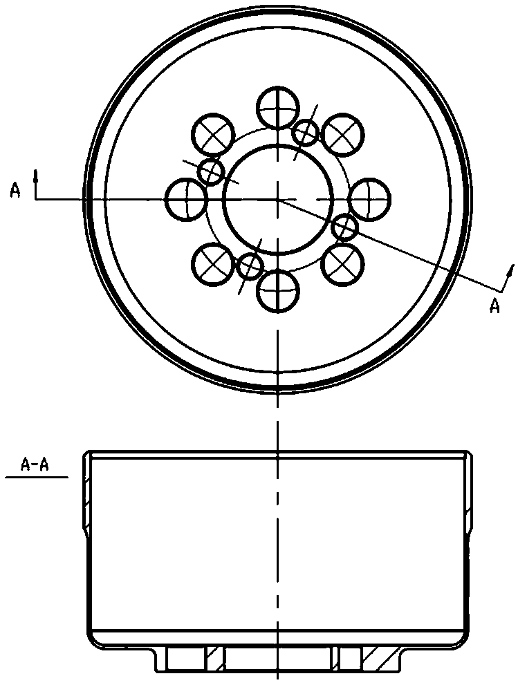
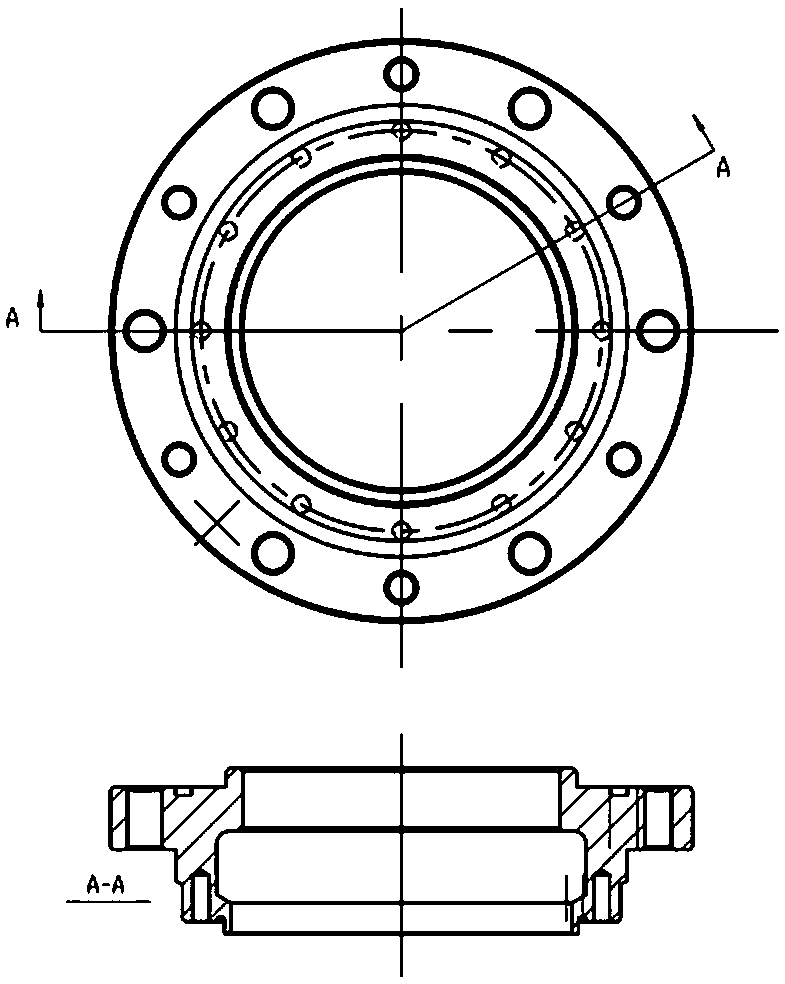

Image

  • Flexible gear and harmonic reducer with flexible gear and rigid gear
  • Flexible gear and harmonic reducer with flexible gear and rigid gear
  • Flexible gear and harmonic reducer with flexible gear and rigid gear

Examples


Embodiment 1

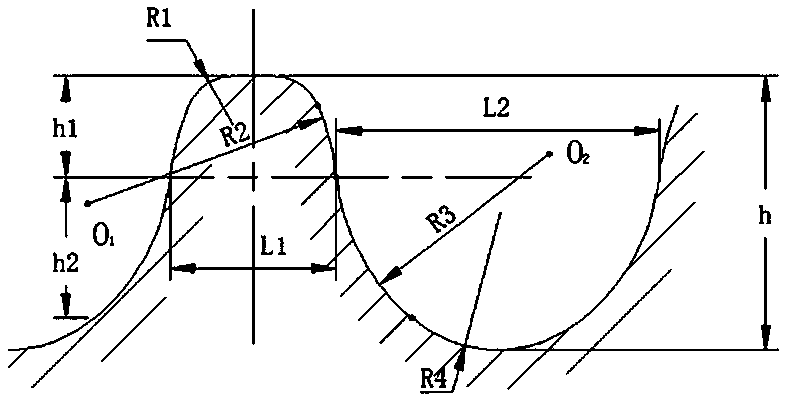
[0025] A harmonic reducer adopts the above technical scheme, in which the flexible wheel parameters are: R1 is 0.1mm, R2 is 0.5171mm, R3 is 0.3426mm, R4 is 0.1851mm, L1 is 0.3439mm, L2 is 0.4466mm, and h1 is 0.1583mm, h2 is 0.2417mm, h is 0.5164mm; the rigid wheel parameters are: R5 is 0.05mm, R6 is 0.5176mm, R7 is 0.6370mm, R8 is 0.1202mm, L3 is 0.3415mm, L4 is 0.4489mm, and h3 is 0.1233mm, h4 is 0.2571mm, H is 0.4940mm.

Embodiment 2

[0027] On the basis of the first embodiment, the parameters of the flexible wheel are changed to: R1 is 0.2mm, R2 is 0.0.6171mm, L1 is 0.5439mm, L2 is 0.6466mm, h1 is 0.2583mm, h2 is 0.3417mm; The parameters are changed to: R7 is 0.7370mm, R8 is 0.2202mm, L3 is 0.5415mm, L4 is 0.6489mm, h3 is 0.2233mm, and h4 is 0.3571mm.

Embodiment 3

[0029] On the basis of Example 1, the parameters of the flexible wheel are changed to: R1 is 0.15mm, R2 is 0.6071mm, L1 is 0.4398mm, L2 is 0.5315mm, h1 is 0.2057mm, h2 is 0.2678mm; the rigid wheel is changed to some parameters Change to: R7 is 0.6756mm, R8 is 0.1987mm, L3 is 0.4322mm, L4 is 0.5576mm, h3 is 0.1866mm, and h4 is 0.3056mm.


PUM

PropertyMeasurementUnit
Radius sizeaaaaaaaaaa
Radial heightaaaaaaaaaa

Abstract

The invention relates to a flexible gear and a harmonic reducer with the flexible gear and a rigid gear. When not stressed, flexible gear teeth on the flexible gear and rigid gear teeth on the rigid gear maintain surface contact in a complete mesh state or a semi-mesh state, and after stressed, the flexible gear teeth on the flexible gear and the rigid gear teeth on the rigid gear are turned intosurface contact in the complete mesh state or the semi-mesh state, so that edge mesh and sharp point mesh can be avoided, the situation that serious tooth surface abrasion generated when the flexiblegear and the rigid gear are engaged is effectively avoided, and formation of an oil film is facilitated; and furthermore, stress concentration at an abraded part can be avoided, the bearing strength of the flexible gear and the rigid gear can be ensured, and the service lives of the flexible gear and the rigid gear can be easily prolonged.

Description

Technical field [0001] The invention relates to a flexible wheel, a rigid wheel matched with the flexible wheel and a harmonic reducer with the flexible wheel and the rigid wheel. Background technique [0002] The harmonic reducer is mainly composed of four basic components: a wave generator, a flexible wheel, and a rigid wheel. It is a kind of flexible wheel that is equipped with a flexible bearing to make the flexible wheel produce controllable elastic deformation and mesh with the rigid wheel for transmission. Gear transmission for movement and power. The existing harmonic reducer deforms the flexspline through the action of the wave generator, and forces the teeth of the flexspline part to mesh with the teeth of the rigid part. Edge meshing and sharp-point meshing usually occur at the meshing position. , It is easy to produce serious wear at the edge meshing and sharp point meshing, which is not conducive to the formation of oil film on the surface of the rigid wheel and the...

Claims


Application Information

Patent Timeline
IPC IPC(8): F16H49/00F16H55/17F16H55/08F16H57/023
CPCF16H49/001F16H55/0833F16H55/088F16H55/17F16H57/023
Inventor 邱楚锋
Owner 广州市新豪精密科技有限公司
Learn More