
Static-dynamic mixed oil film bearing

A mixed oil, dynamic and static pressure technology, applied in the direction of bearings, shafts and bearings, bearing components, etc., can solve the problems of contact wear between the main shaft and the bearing, low bearing capacity, and is only suitable for occasions with constant external loads, etc., to improve the rotation speed Accuracy, improvement of dynamic pressure effect, improvement of oil film rigidity and effect of homogenization error

Inactive Publication Date: 2009-11-11
重庆西门雷森机械工程技术服务有限公司
View PDF1 Cites 26 Cited by
  • Summary
  • Abstract
  • Description
  • Claims
  • Application Information

AI Technical Summary

Problems solved by technology

The bearing of this structural form is only a simple combination of dynamic pressure and static pressure, and its structure is complex and its bearing capacity is not high.
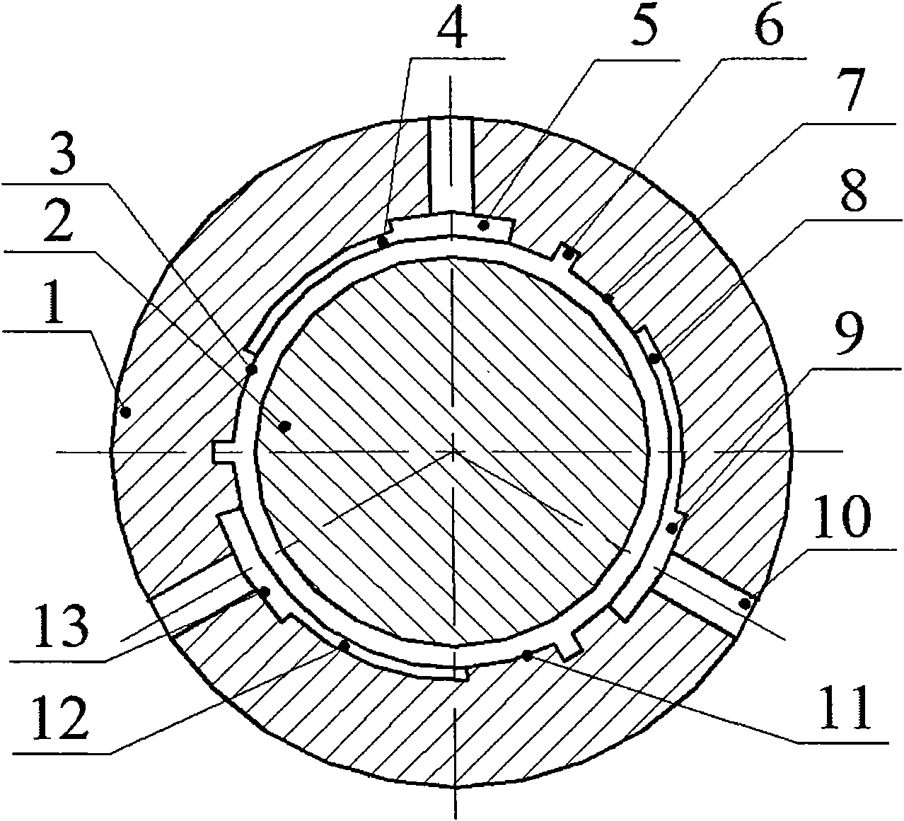
In recent years, some people have designed and developed dynamic and static pressure bearings with mixed effects of dynamic pressure and static pressure, such as the dynamic and static pressure bearing for the main shaft of the grinding wheel of the roll grinder with the patent number ZL200520074843.2. chamber and a dynamic pressure chamber, the external load is carried by the joint action of the above-mentioned oil chamber when starting and working, which makes full use of the principle of the mixed effect of dynamic pressure and static pressure, and has high oil film rigidity, but the dynamic and static Pressure bearings are prone to contact wear between the main shaft and the bearing during the start-up phase. Under operating conditions, the dynamic pressure effect is not significant enough. In addition, this bearing is only suitable for occasions with constant external loads, and is not suitable for mechanical equipment spindle systems with alternating loads. use

Method used


Image

  • Static-dynamic mixed oil film bearing
  • Static-dynamic mixed oil film bearing
  • Static-dynamic mixed oil film bearing

Examples


Embodiment Construction

[0013] Below in conjunction with accompanying drawing and embodiment technical scheme of the present invention is further described as follows:

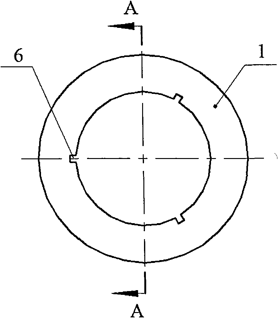
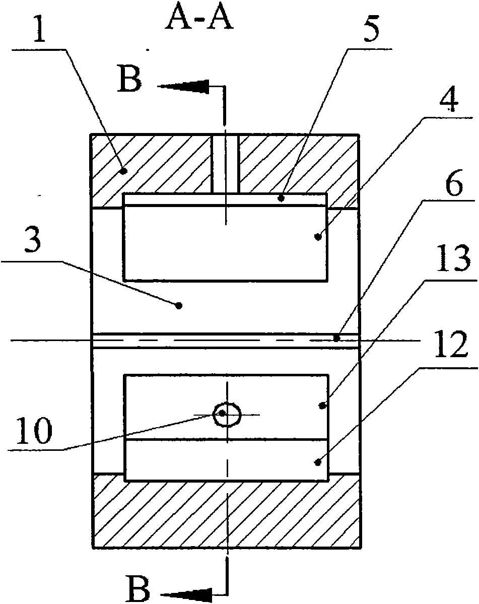
[0014] The structure of the present invention includes a dynamic and static pressure mixed oil film bearing 1 and a main shaft 2, and is characterized in that the inner hole surface of the dynamic and static pressure mixed oil film bearing 1 is provided with three static pressure chambers at 120° to each other, that is, the upper static pressure chamber 5, the front static pressure chamber chamber 9 and rear static pressure chamber 13, the pressure oil enters the above static pressure chambers through the oil inlet hole 10, and the pressure oil returns to the oil through three axial oil return grooves 6, and there are three There are two stepped chambers at 120° each other, namely the upper stepped chamber 4, the front stepped chamber 8 and the rear stepped chamber 12. The oil sealing surface between the above stepped chamber and the ...


PUM


Abstract

The invention discloses a static-dynamic mixed oil film bearing, which comprises a static-dynamic mixed oil film bearing 1, a main shaft 2, a return chute 6, and an oil inlet hole 10. The static-dynamic mixed oil film bearing is characterized in that the surface of an inner hole of the static-dynamic mixed oil film bearing 1 is provided with three static cavities which mutually form 120 degrees; pressure oil enters each static cavity through the oil inlet hole 10; the pressure oil returns through three coaxial return chutes 6; three step holes mutually forming 120 degrees are arranged between the static cavities and the coaxial return chutes 6; and three dynamic cavities are formed on the oil seal surface between the step cavities and the coaxial return chutes 6. The static-dynamic mixed oil film bearing better solves the contact problem between the main shaft and the static-dynamic mixed oil film bearing when the main shaft is started, and greatly improves the dynamic pressure effect of the static-dynamic mixed oil film bearing when in operation work condition and therefore obtains an ideal dynamic pressure effect, can greatly improve the rigidity of the oil membrane and the effect of homogenizing errors, and can greatly improve the return precision of a main shaft system.

Description

Technical field: [0001] The invention belongs to mechanical transmission bearings, in particular to a dynamic and static pressure mixed oil film bearing used in a main shaft system of mechanical equipment bearing alternating loads. Background technique: [0002] At present, the main structural form of the dynamic and static pressure bearings used in enterprises is to set the dynamic pressure chamber and the static pressure chamber at a certain position in the axial direction. Bearing external load; when entering normal operating conditions, the pressure oil in the static pressure chamber is closed, and the dynamic pressure of the dynamic pressure chamber bears the external load. The bearing of this structural form is only a simple combination of dynamic pressure and static pressure, and its structure is complex and its bearing capacity is not high. In recent years, some people have designed and developed dynamic and static pressure bearings with mixed effects of dynamic pre...

Claims


Application Information

Patent Timeline
IPC IPC(8): F16C32/06F16C33/10
Inventor 王勇勤严兴春江桂云
Owner 重庆西门雷森机械工程技术服务有限公司
Learn More