
Switching power supply detection circuit

A switching power supply and detection circuit technology, applied in the direction of power supply testing, electronic circuit testing, measuring electricity, etc., can solve the problems of complex system, high power consumption, and high AD resource requirements, achieve adjustable control logic, reduce interface requirements, and be suitable for good effect

Pending Publication Date: 2020-02-21
HANGZHOU BMSER TECH
View PDF0 Cites 0 Cited by
  • Summary
  • Abstract
  • Description
  • Claims
  • Application Information

AI Technical Summary

Problems solved by technology

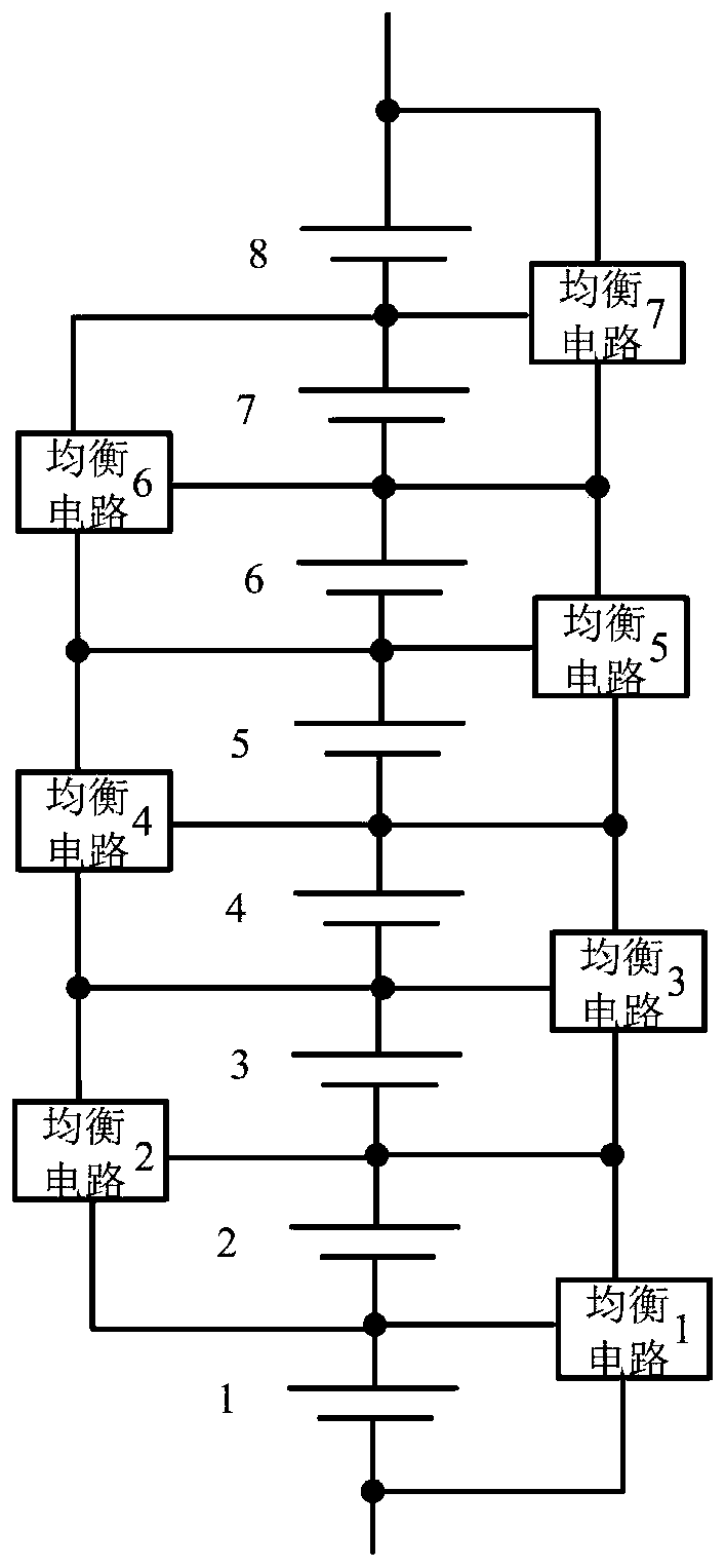
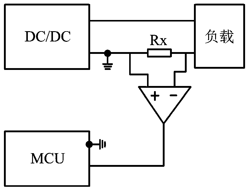
[0005] In the above equalization circuit detection method, one detection circuit needs to correspond to one AD interface, which requires high AD resources of the MCU; and devices with high power consumption such as sampling resistors are required; in addition, the reference grounds of each active equalization module are different, and an isolation circuit is required , so the detection of each active equalization module requires a detection circuit, an isolated power supply, and an analog or digital signal isolation circuit, and the system is complex

Method used


Image

  • Switching power supply detection circuit
  • Switching power supply detection circuit
  • Switching power supply detection circuit

Examples


Embodiment Construction

[0043] Some preferred embodiments of the present invention will be described below in conjunction with the accompanying drawings, and the technical solutions in the embodiments of the present invention will be clearly and completely described. However, the described embodiments are part of the embodiments of the present invention, not all of them. example. Based on the embodiments of the present invention, all other embodiments obtained by persons of ordinary skill in the art without creative efforts fall within the protection scope of the present invention.

[0044] The first and second in the first terminal, the second terminal, the first power terminal, the second power terminal, etc. in this application are only for convenience to describe the content of the present invention, and are not used for limiting purposes.

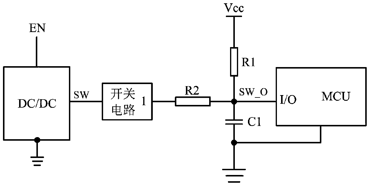
[0045] refer to image 3 It is a schematic diagram of the first embodiment of the detection circuit of the switching power supply according to the present i...


PUM


Abstract

The invention discloses a switching power supply detection circuit that generates an output voltage signal associated with the working state of a switching power supply by receiving a switching pointsignal representing the working state of the switching power supply, and an upper control machine judges whether the switching power supply fails or not by matching the level states of the output voltage signal and a preset signal. By means of the detection circuit, time-sharing detection can be conducted according to requirements, the interface requirement for the upper control machine is lowered, and the detection circuit is simple in structure, adjustable in control logic and good in applicability.

Description

technical field [0001] The invention relates to the technical field of battery management, and more specifically, to a detection circuit of a switching power supply. Background technique [0002] In a large-scale battery system with a large demand for energy storage, the voltage and capacity of a single battery are difficult to meet the requirements, and it is often necessary to combine multiple single batteries in a certain series-parallel manner to form a battery pack for use in large-scale systems. However, because the production environment, process parameters, raw materials, etc. are difficult to be completely consistent, each single battery produced will have differences, and due to the difference in the use environment, the differences between single batteries will increase over time. expand. [0003] In order to reduce the inconsistency of the battery pack during use, it is necessary to add a balancing circuit to the battery, usually through an active or passive bal...

Claims


Application Information

Patent Timeline
Patent Type & Authority Applications(China)
IPC IPC(8): G01R31/40G01R31/396G01R31/385G01R31/28
CPCG01R31/2843G01R31/385G01R31/396G01R31/40
Inventor 奚淡基童成涛黎夏周逊伟
Owner HANGZHOU BMSER TECH
Learn More