
Gravity self-adjusting hydraulic pressure stabilizing device

A voltage stabilizer and self-regulating technology, applied in water shower coolers, direct contact heat exchangers, heat exchanger types, etc., can solve the problems of increased water outlet resistance of pipelines, increased energy consumption of circulation systems, and high installation requirements , to ensure the balance of internal and external pressure, solve the problem of negative pressure at the outlet, and maintain the balance of pipeline resistance.

Pending Publication Date: 2020-02-21
江苏多纬智控科技有限公司
View PDF0 Cites 1 Cited by
  • Summary
  • Abstract
  • Description
  • Claims
  • Application Information

AI Technical Summary

Problems solved by technology

[0006] The traditional solution is to adjust the initial resistance by adjusting the valves on the water inlet branches. The result is still that the effect is difficult to guarantee. Even if the water resistance bodies of all the branch pipes are adjusted to be consistent, the effect cannot be guaranteed. Because the problem lies in which pipe comes out of the water first, it will cause the above problems
And when the water inlet valve is adjusted, the water outlet resistance on the entire pipeline will be greatly increased, which will increase the energy consumption of the circulation system.
[0007] According to the above situation, a small flow external water resistance adjustment device was invented, but the existing small flow external water resistance adjustment device 1. The volume is large; 2. It is arranged on the upper end of the cooling tower, protruding from the cooling tower, which is easy to cause lightning; 3. It is inconvenient to install and must be installed at the corner, which consumes manpower; 3. When there is a large amount of water, the water resistance is too large, and the energy consumption of the circulation system is high; 4. It cannot solve the problem of negative pressure at the outlet; if the outlet pipe is too long, the effect is not good; 5. 1. The inlet and outlet must be vertical and cannot be installed in horizontal pipes; 6. High installation requirements and poor adaptability (cannot be applied to built-in cooling towers); 7. High cost (in order to overcome the problems of pipeline vibration and wind resistance, high-cost material) is poor in economy, and a gravity self-adjusting hydraulic pressure stabilizing device is now designed to solve the above problems

Method used


Image

  • Gravity self-adjusting hydraulic pressure stabilizing device
  • Gravity self-adjusting hydraulic pressure stabilizing device
  • Gravity self-adjusting hydraulic pressure stabilizing device

Examples


Embodiment 1

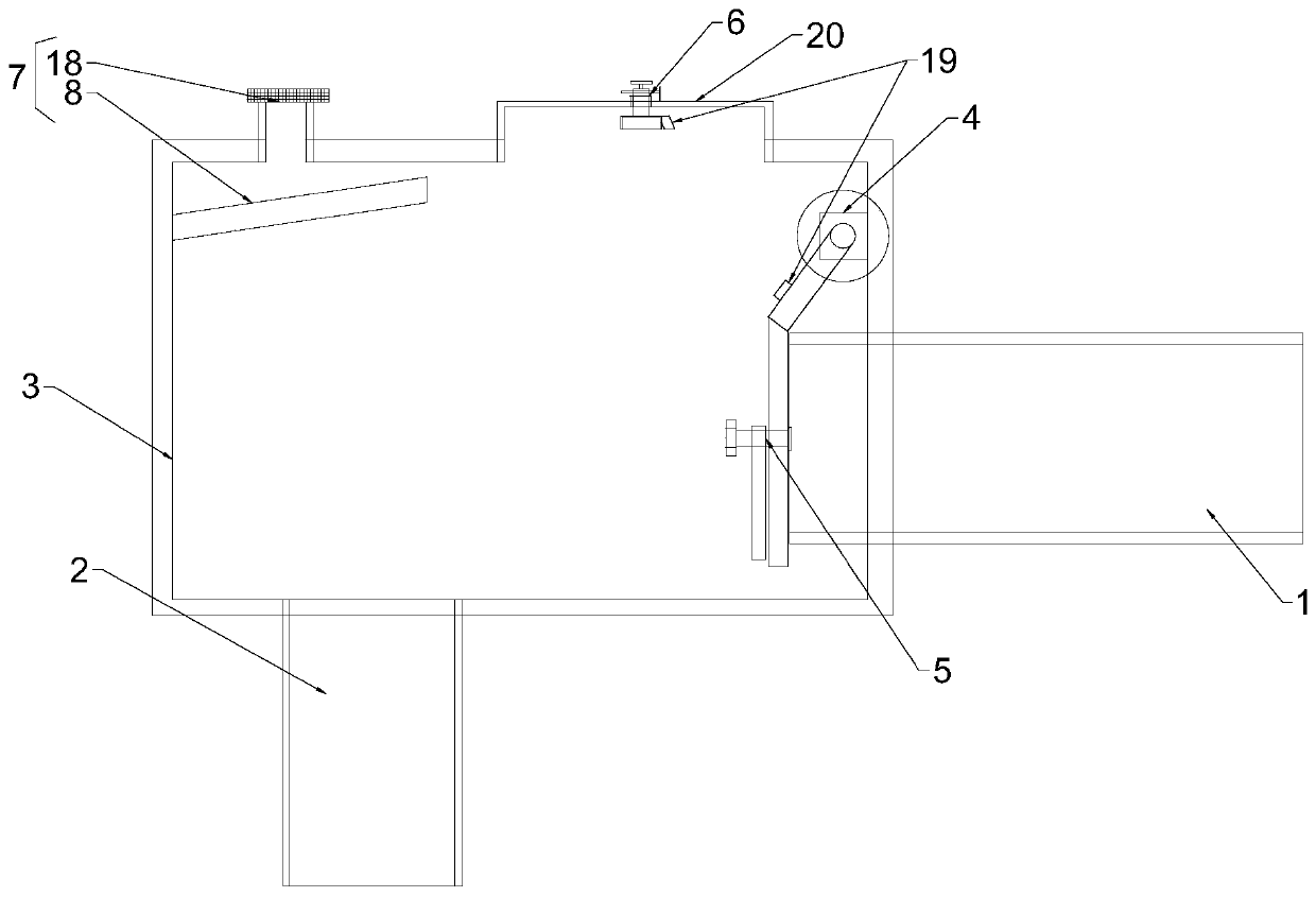
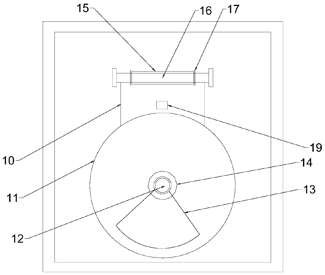
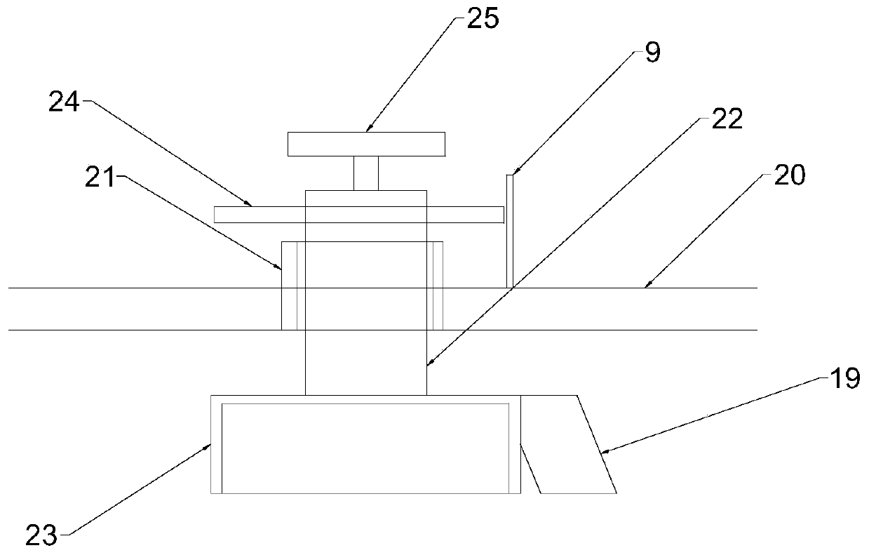
[0028] Example 1: See Figure 1-3 , the present invention provides a technical solution: a gravity self-adjusting hydraulic pressure stabilizing device, including a water inlet pipe 1, an outlet pipe 2, an adjustment box 3, a fixed fulcrum 4 with a rotating mechanism, a flow limiting device 5, an external water resistance Adjusting device 6, pressure balance device 7, above the water inlet inside the regulating box 3 is provided with a fixed fulcrum 4 with a rotating mechanism, a flow limiting device 5 is arranged on the fixed fulcrum 4 with a rotating mechanism, the limiting The flow device 5 includes a connecting piece 10, a water flow resistance plate 11, and a gravity resistance adjustment block 13. The water flow resistance plate 11 is installed on the fixed fulcrum 4 with a rotating mechanism through the connecting piece 10, and the water flow resistance plate 11 and the connecting piece 10 are connected at a certain angle, the water flow resistance plate 11 is placed on...

Embodiment 2

[0034] Example 2: see Figure 4, the present invention provides a technical solution: a gravity self-adjusting hydraulic pressure stabilizing device, including a water inlet pipe 1, an outlet pipe 2, an adjustment box 3, a fixed fulcrum 4 with a rotating mechanism, a flow limiting device 5, an external water resistance Adjusting device 6, pressure balance device 7, above the water inlet inside the regulating box 3 is provided with a fixed fulcrum 4 with a rotating mechanism, a flow limiting device 5 is arranged on the fixed fulcrum 4 with a rotating mechanism, the limiting The flow device 5 includes a connecting piece 10, a water flow resistance plate 11, and a gravity resistance adjustment block 13. The water flow resistance plate 11 is installed on the fixed fulcrum 4 with a rotating mechanism through the connecting piece 10, and the water flow resistance plate 11 and the connecting piece 10 is connected at a certain angle, and the water flow resistance plate 11 is placed on...


PUM


Abstract

The invention belongs to the technical field of adjusting equipment, and particularly discloses a gravity self-adjusting hydraulic pressure stabilizing device. The device comprises a water inlet pipeline, a water outlet pipeline, an adjusting box, a fixed fulcrum with a rotary mechanism, a flow limiting device, an external water resistance adjusting device and a pressure balancing device. The fixed fulcrum with the rotary mechanism is arranged above a water inlet in the adjusting box, the flow limiting device is arranged on the fixed fulcrum with the rotary mechanism and comprises a connectingpiece, a water flow resistance plate and a gravity resistance adjusting block, the water flow resistance plate is mounted on the fixed fulcrum with the rotary mechanism through the connecting piece,the water flow resistance plate is connected with the connecting piece at an angle, the water flow resistance plate is vertically placed on a water inlet of the water inlet pipeline, and the gravity resistance adjusting block is arranged on the water flow resistance plate.

Description

technical field [0001] The invention relates to the related field of regulating equipment, in particular to a gravity self-regulating hydraulic pressure stabilizing device. Background technique [0002] The cooling tower system must realize the maximum cooling area utilization operation, which puts forward new requirements for the hardware conditions of the cooling tower. Especially in the cooling tower system during the low and medium load period, because the total operating load does not reach the maximum load of the cooling tower design, the traditional cooling tower is not suitable and the flow rate drops, and part of the cooling area cannot be effectively used. Inability to fully prioritize the use of cooling tower cooling area for operation. [0003] Why can't the area of ​​the cooling tower be fully utilized during low and medium load periods? The main reason is that the cooling tower system is composed of multiple independent cooling towers. When the actual operati...

Claims


Application Information

Patent Timeline
Patent Type & Authority Applications(China)
IPC IPC(8): F28F25/04
CPCF28F25/04
Inventor 张红星张可邑黄顺玉韩斌斌陈科豪
Owner 江苏多纬智控科技有限公司
Learn More