
Floating rubber dam

A rubber dam and floating technology, applied in water conservancy projects, sea area projects, coastline protection, etc., can solve problems such as construction difficulties, maintenance and replacement difficulties, affecting landscape and navigation, etc., to reduce damage or impact, and facilitate replacement and maintenance Effect

Pending Publication Date: 2020-02-21
JIANGSU TAIHU PLANNING & DESIGN INST OF WATER RESOURCES CO LTD
View PDF0 Cites 3 Cited by
  • Summary
  • Abstract
  • Description
  • Claims
  • Application Information

AI Technical Summary

Problems solved by technology

It is not suitable to set a fixed water level for a navigable river with a water head difference, a large width, a river that cannot be suspended for construction, or a river with restricted excavation on both sides of the river and where flood control or water diversion control buildings need to be installed. On the one hand, the construction of the water conservancy gate project is difficult, on the other hand, the fixed water conservancy gate affects the landscape and navigation, and it is difficult to maintain and replace it.

Method used


Image

  • Floating rubber dam
  • Floating rubber dam

Examples


Embodiment 1

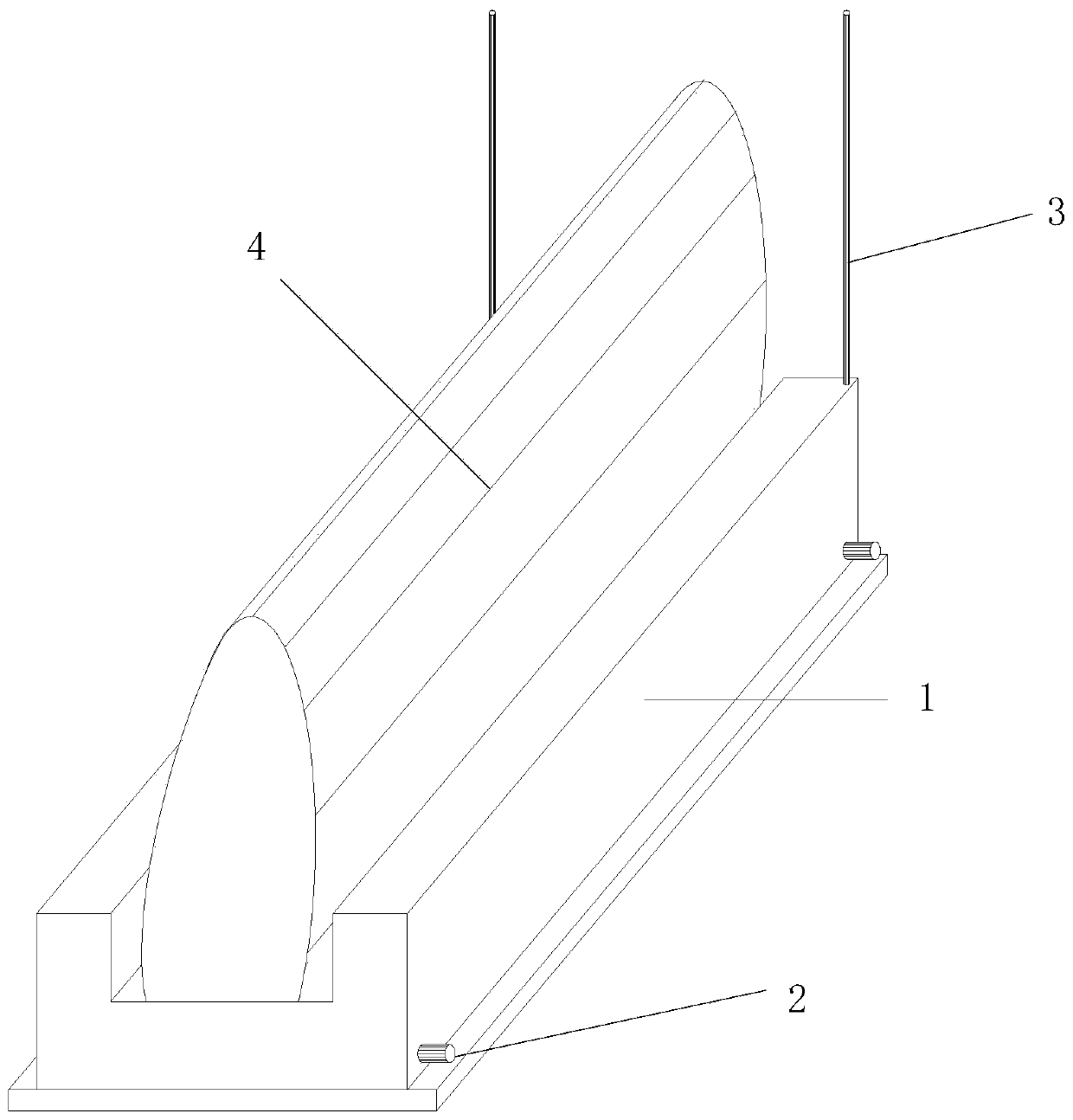
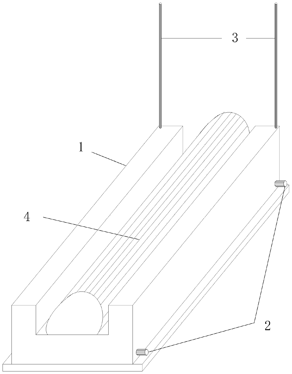
[0044] Such as Figure 1 to Figure 2 As shown, the invention provides a floating rubber dam, comprising:

[0045] A buoyant tank 1, the buoyant tank 1 is used to be placed on the bottom of the water, the side wall of the buoyant tank 1 is provided with a filling and discharging pipe 2, and the top of the buoyant tank 1 is provided with a vent pipe 3, and the vent pipe 3 protrudes from the water surface;

[0046] The dam bag 4, the dam bag 4 is connected to the top of the buoyancy tank 1.

[0047] In this embodiment, the cross section of the buoyancy tank 1 is concave, and the dam bag 4 is connected in the middle of the concave.

[0048] The bottom of the dam bag 4 is provided with connecting plates extending to both sides, and the middle of the buoyancy tank 1 is provided with a pressing plate, and the connecting plate is located below the pressing plate. The height of the top surface of the dam bag 4 when not filling with water does not exceed the height of the top surface ...

Embodiment 2

[0059] The difference between this embodiment and embodiment 1 is that

[0060] In this embodiment, the filling and draining pipe 2 is used to communicate with the filling and draining system, the dam bag 4 is connected to the filling and exhausting system, and the bottom of the dam bag 4 is provided with a pressure regulating pipe protruding from the water surface. When the dam bag 4 is inflatable, the dam bag 4 is not connected to the buoyancy tank 1, and the dam bag 4 is connected to the inflation and exhaust system alone to realize inflation and exhaust, and the dam bag 4 is provided with a pressure regulating pipe to avoid excessive inflation pressure And burst.


PUM

PropertyMeasurementUnit
Lengthaaaaaaaaaa
Widthaaaaaaaaaa
Heightaaaaaaaaaa

Abstract

The invention relates to a floating rubber dam. The floating rubber dam comprises a floating box, and a dam bag; wherein the floating box is used for being placed at the bottom of water, the side wallof the floating box is provided with a filling and discharging pipe, the top of the floating box is provided with a ventilation pipeline, and the ventilation pipeline extends out of the water surface; and the dam bag is connected to the top of the floating box. According to the floating rubber dam, the floating box sinks by filling water in the floating box through the filling and discharging pipe; the water can be injected into the dam bag to enable the dam bag to be inflated to control water flow, and the water in the dam bag is discharged through the filling and discharging pipe to enablethe dam bag to be shrunk, so that navigation is restored; and the floating rubber dam is not limited by construction conditions, replacement and maintenance are convenient, and the damage or influenceon surrounding buildings caused by construction excavation is reduced.

Description

technical field [0001] The invention belongs to the technical field of water conservancy river regulation, and more specifically relates to a floating rubber dam. Background technique [0002] At present, the structure of large-scale water conservancy gates at home and abroad generally adopts floating body doors, floating box doors, lying down doors, hanging doors, fan-shaped revolving doors, mirror doors, floating box doors, plane arc doors, etc. Each gate type has its own characteristics, and the corresponding gate type will be selected after considering factors such as project location, construction conditions, maintenance, operation management requirements, and navigation. It is not suitable to set a fixed water level for a navigable river with a water head difference, a large width, a river that cannot be suspended for construction, or a river with restricted excavation on both sides of the river and where flood control or water diversion control buildings need to be in...

Claims


Application Information

Patent Timeline
IPC IPC(8): E02B7/00
CPCE02B7/005
Inventor 常语锋顾晓峰杭丹吕犇管义兵张旭
Owner JIANGSU TAIHU PLANNING & DESIGN INST OF WATER RESOURCES CO LTD
Learn More