Yarn winding mechanism of roving machine and roving machine production line with same

A technology of roving frame and frame, which is applied in the direction of spinning machine, continuous winding spinning machine, textile and paper making, etc., which can solve the problems of high labor participation and high labor cost, and reduce work intensity, Save labor costs and improve personal safety

Active Publication Date: 2020-02-21
龙海冠鸿纺织有限公司
View PDF16 Cites 1 Cited by
  • Summary
  • Abstract
  • Description
  • Claims
  • Application Information

AI Technical Summary

Problems solved by technology

[0004] In the prior art, similar to the above-mentioned roving machine, the wool sliver is rewound by driving the winding shaft to rotate. When the wool sliver needs to be replaced, the staff needs to take the winding shaft out of the frame (equivalent to the first outer casing and the combination of the second outer casing), and then manually reinstall the winding shaft on the frame to prepare for the next winding work, and, in order to prevent the wool strip from rubbing against the winding shaft when picking and placing the wool strip, generally Yarn bobbins will be placed on the rewinding shaft. In the above-mentioned rewinding process, the degree of manual participation is high, resulting in high labor costs, so it needs to be improved

Method used


Image

  • Yarn winding mechanism of roving machine and roving machine production line with same
  • Yarn winding mechanism of roving machine and roving machine production line with same
  • Yarn winding mechanism of roving machine and roving machine production line with same

Examples


Embodiment Construction

[0049] The present invention will be described in detail below in conjunction with the accompanying drawings and embodiments.

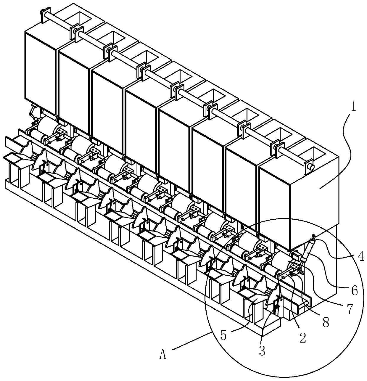
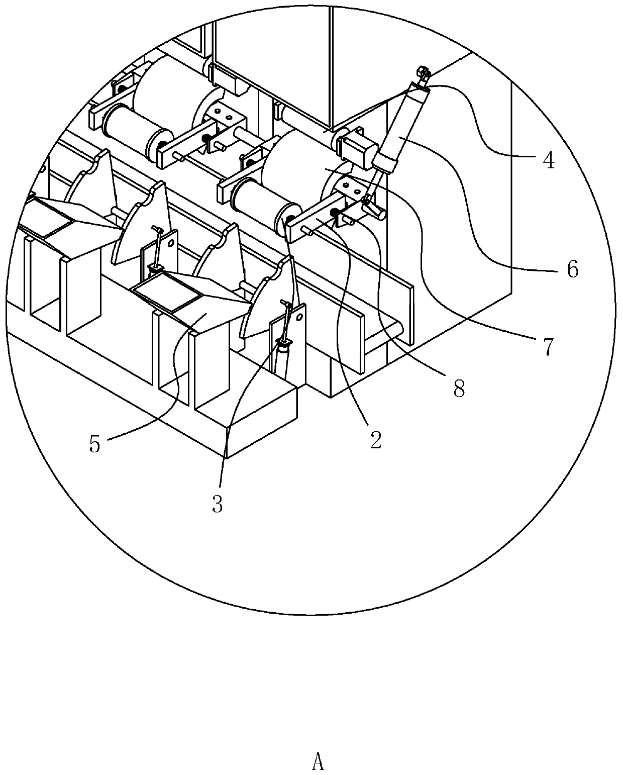
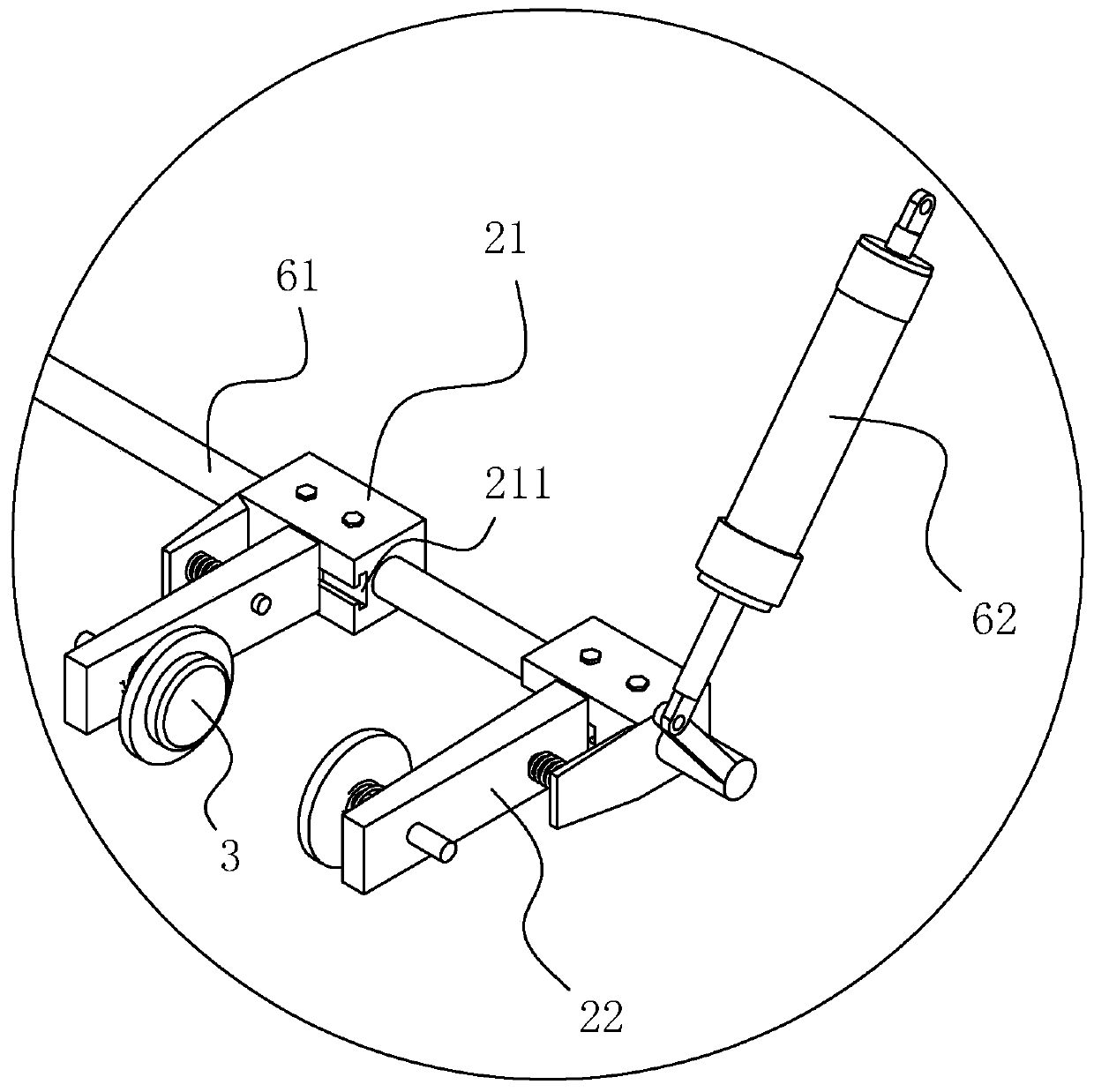
[0050] A slubbing frame winding mechanism, combined with figure 1 and figure 2 As shown, it includes two clamping parts 3 arranged on the frame 1 for respectively clamping the left and right ends of the yarn bobbin, rotatably connected to the frame 1 and rotatably connected with the clamping part 3 for controlling the clamping part 3 Clamping arm assembly 2 for clamping or loosening the bobbin, set on the frame 1 and capable of engaging with the bobbin clamped by the clamping arm assembly 2 for driving the bobbin to rotate itself, the friction roller assembly 4, set on On the frame 1, the can changer assembly 5 for providing new yarn reels for the jig arm assembly 2 is arranged on the frame 1 for driving the jig arm assembly 2 to rotate so that the jig arm assembly 2 can access the cannula changer assembly 5 The rotating shaft mechanism 6 of the ne...


PUM


Abstract

The invention discloses a yarn winding mechanism of a roving machine and a roving machine production line with the same, and relates to the technical field of roving machines. The yarn winding mechanism is characterized by comprising two clamping pars which are arranged on a frame and are used for respectively clamping the left end and right end of a bobbin, a clamping arm assembly which is rotatably connected to the frame, is rotatably connected with the clamping parts and is used for controlling the clamping parts to clamp or loosen the bobbin, and a frictional rubber roller assembly which is arranged on the frame and can be meshed with the bobbin clamped by the clamping arm assembly so as to drive the bobbin to rotate, a bobbin changing assembly arranged on the frame and used for providing a new bobbin for the clamping arm assembly, a rotating shaft mechanism arranged on the frame and used for driving the clamping arm assembly to rotate so as to enable the clamping arm assembly to pick the new bobbin provided by the bobbin changing assembly, an outer supporting assembly arranged on the frame and used for driving the clamping arm assembly to release the bobbin which a roving wound on, and an inner pushing assembly arranged on the clamping arm assembly so as to drive the two clamping parts to cooperate to clamp the bobbin. The yarn winding mechanism and the roving machine production line have the advantage of reduced labor cost.

Description

technical field [0001] The present invention relates to the technical field of roving frame, more specifically, it relates to a winding mechanism of roving frame. Background technique [0002] A roving frame is a spinning machine that turns sliver into roving. The main functions of the roving frame are drafting and twisting, and winding the roving into a certain package to meet the processing requirements of the spinning machine. The roving frame is divided into wing roving frame and rubbing roving frame according to the form of twisting mechanism. The feeding form, roving package and the number of spindles of the various roving frames are different, but the machine structure and function are roughly the same. [0003] The Chinese patent with the authorized notification number CN208395354U discloses a fast-type high-efficiency wool top slubbing machine, which includes a first outer shell and a second outer shell. The top of the first outer shell is screwed and fixed with a ...

Claims


Application Information

Patent Timeline
IPC IPC(8): D01H1/36D01H1/20D01H9/02
CPCD01H1/20D01H1/36D01H9/02
Inventor 陈冠宇候艺端
Owner 龙海冠鸿纺织有限公司
Why Eureka
Try Eureka