
Coiling device for sliver can conversion, textile machinery with soiling device and combination

A technology of textile machinery and cans, which is applied in the field of textile machinery and equipment, can solve the problems of high cost and high cost, achieve high production efficiency, save machine transformation costs, and simplify design

Pending Publication Date: 2020-02-21
SAURER (JIANGSU) TEXTILE MASCH CO LTD
View PDF0 Cites 1 Cited by
  • Summary
  • Abstract
  • Description
  • Claims
  • Application Information

AI Technical Summary

Problems solved by technology

[0003] Circular cans are widely used, while rectangular cans are limited in application. The reason is that traditional draw frames are mostly designed to adapt to circular cans. If rectangular cans are used, coiling is required. The driving system will make the cost 5% higher than that of the traditional draw frame; the second is to be able to adapt to the current circular can coil driving system, the cost of rectangular cans on the market is high, and the cost is often round 3 times the barrel

Method used


Image

  • Coiling device for sliver can conversion, textile machinery with soiling device and combination
  • Coiling device for sliver can conversion, textile machinery with soiling device and combination
  • Coiling device for sliver can conversion, textile machinery with soiling device and combination

Examples


Embodiment 1

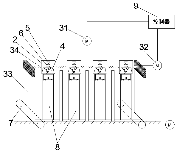
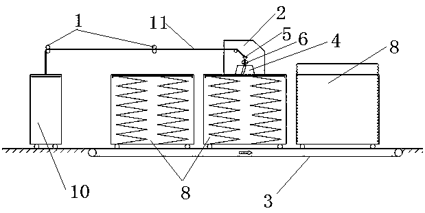
[0039] This embodiment describes a coiling device for can conversion, which comprises at least one rectangular can 8 for storing fiber sliver 11, for driving said coiling disc 4 relative to said rectangular can. The driving mechanism of the relative movement of the bar can 8, the feed of the coiled disc 4 comes from at least one circular bar can 10 for storing fiber strips 11, and the output of the coiled disc 4 is stored in at least one for storing The rectangular can 8 of the fiber sliver 11, the driving mechanism is used for when the coiling device is in working condition, the coiling disc 4 is driven by the driving mechanism to form an axial direction above the rectangular can 8. movement, and at the same time make a linear reciprocating motion in the horizontal plane above the rectangular can 8, for converting the fiber strips 11 in the circular can 10 into the rectangular can 8.

[0040] Such as figure 1 As shown, the coiling device can include a guide frame 1, a fixed ...

Embodiment 2

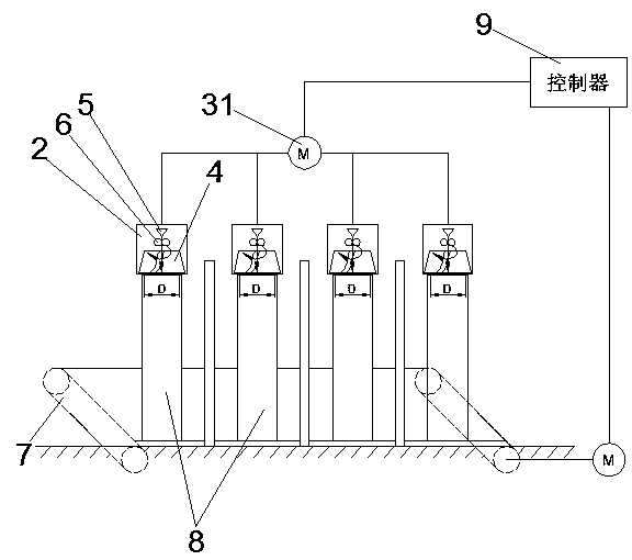
[0050] This embodiment describes a coiling device for can conversion, which comprises at least one rectangular can 8 for storing fiber sliver 11, for driving said coiling disc 4 relative to said rectangular can. The driving mechanism of the relative movement of the bar can 8, the feed of the coiled disc 4 comes from at least one circular bar can 10 for storing fiber strips 11, and the output of the coiled disc 4 is stored in at least one for storing The rectangular bar can 8 of the fiber sliver 11, the driving mechanism is used for when the sliver coiling device is in working condition, the coiling disc 4 is driven by the driving mechanism to only act as a shaft on the top of the rectangular bar can 8 and at the same time, the driving mechanism drives and controls the rectangular can 8 to do linear reciprocating motion in the horizontal plane below the coiling disc 4, for converting the fiber strips 11 in the circular cans 10 into rectangular strips. Inside the cylinder 8.

...

Embodiment 3

[0059] The present embodiment provides a textile machine comprising a coiling device for can conversion as described above. That is, the coiling device for can conversion of the present invention is used as an auxiliary machine of a textile machine, and the structure of the coiling device can be as described in any of the above-mentioned embodiments and will not be repeated here. Before the fiber sliver enters the textile machine, it is transferred from a circular can to a rectangular can, so that the feeding cylinder of the textile machine is a rectangular can with high space utilization and larger capacity, and there is no need to carry out the traditional fiber sliver 11 output textile machine. Any modification, save the cost of machine modification and increase productivity.


PUM


Abstract

The invention relates to a coiling device for sliver can conversion, textile machinery with the soiling device and combination. The coiling device comprises at least one rectangular sliver can and a driving mechanism, each rectangular sliver can is used for sliver storage, and the driving mechanism is used for driving a coiling disc to move relative to the at least one rectangular sliver. Materials fed into the coiling disc come from a round sliver can for sliver storage, and discharged materials of the coiling disc are stored in the at least one rectangular sliver can for sliver storage. Thedriving mechanism is used for driving the coiling disc to perform axial motion and straight reciprocating motion relative to the at least one rectangular sliver at the same time when the coiling device is in an operating state and is used for transferring slivers from the round sliver can into the at least one rectangular sliver. The coiling device can serve as an auxiliary engine for the textilemachinery such as a drawing frame, machine modification cost can be saved, sliver transfer storage between the round sliver can and the rectangular sliver can is realized, and investment can be further saved by application of the coiling device to textile machinery or textile machinery combination.

Description

technical field [0001] The invention relates to textile machinery equipment, in particular to a coiling device for can conversion, a textile machine and a combination thereof. Background technique [0002] In textile machinery such as carding machine, drawing frame and combing machine, cans are commonly used fiber sliver storage devices. Currently, the cans used include round cans and rectangular cans, and the most commonly used is round cans. Because the circular cans are not filled with fiber strips near the circumference and center of the cans during the coiling process, and the coiling form of the rectangular cans is different from that of the circular cans, so the rectangular cans with the same volume can accommodate The fiber sliver weight is about 1.5 times that of the round can, and the rectangular can size can be more suitable for Rotor rotor spinning and Airjet machine layout. [0003] Circular cans are widely used, while rectangular cans are limited in applicatio...

Claims


Application Information

Patent Timeline
Patent Type & Authority Applications(China)
IPC IPC(8): D01G27/00
CPCD01G27/00
Inventor 汤福华石琳
Owner SAURER (JIANGSU) TEXTILE MASCH CO LTD
Learn More