
Efficient aeration sewage treatment pool with bubble eliminating function

A sewage treatment tank and defoaming technology, which is applied in the direction of biological water/sewage treatment, water/sludge/sewage treatment, water aeration, etc., can solve problems such as troublesome, excessive foam defoaming, etc., to improve dissolved oxygen rate, Improve efficiency, good aeration effect

Active Publication Date: 2020-02-21
广州中晟水务环保科技有限公司
View PDF6 Cites 1 Cited by
  • Summary
  • Abstract
  • Description
  • Claims
  • Application Information

AI Technical Summary

Problems solved by technology

[0005] The purpose of the present invention is to provide a high-efficiency aerated sewage treatment tank with defoaming function that can automatically defoam and improve aeration efficiency in view of the problem that there are many foams in the sewage tank and the defoaming is troublesome.

Method used


Image

  • Efficient aeration sewage treatment pool with bubble eliminating function
  • Efficient aeration sewage treatment pool with bubble eliminating function
  • Efficient aeration sewage treatment pool with bubble eliminating function

Examples


Embodiment 1

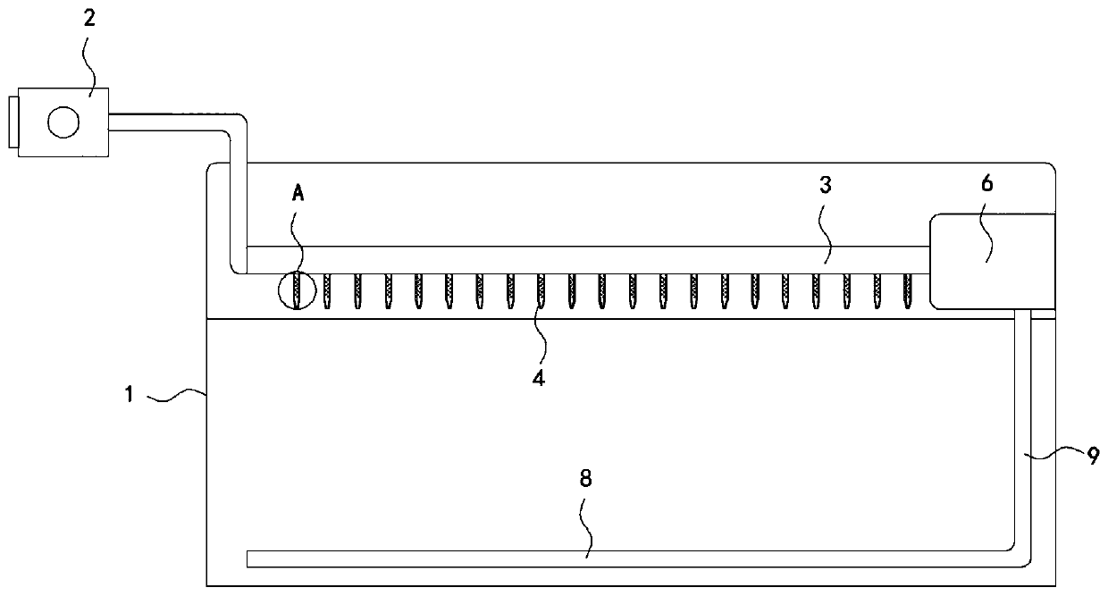
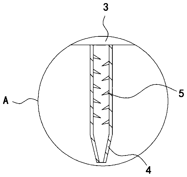
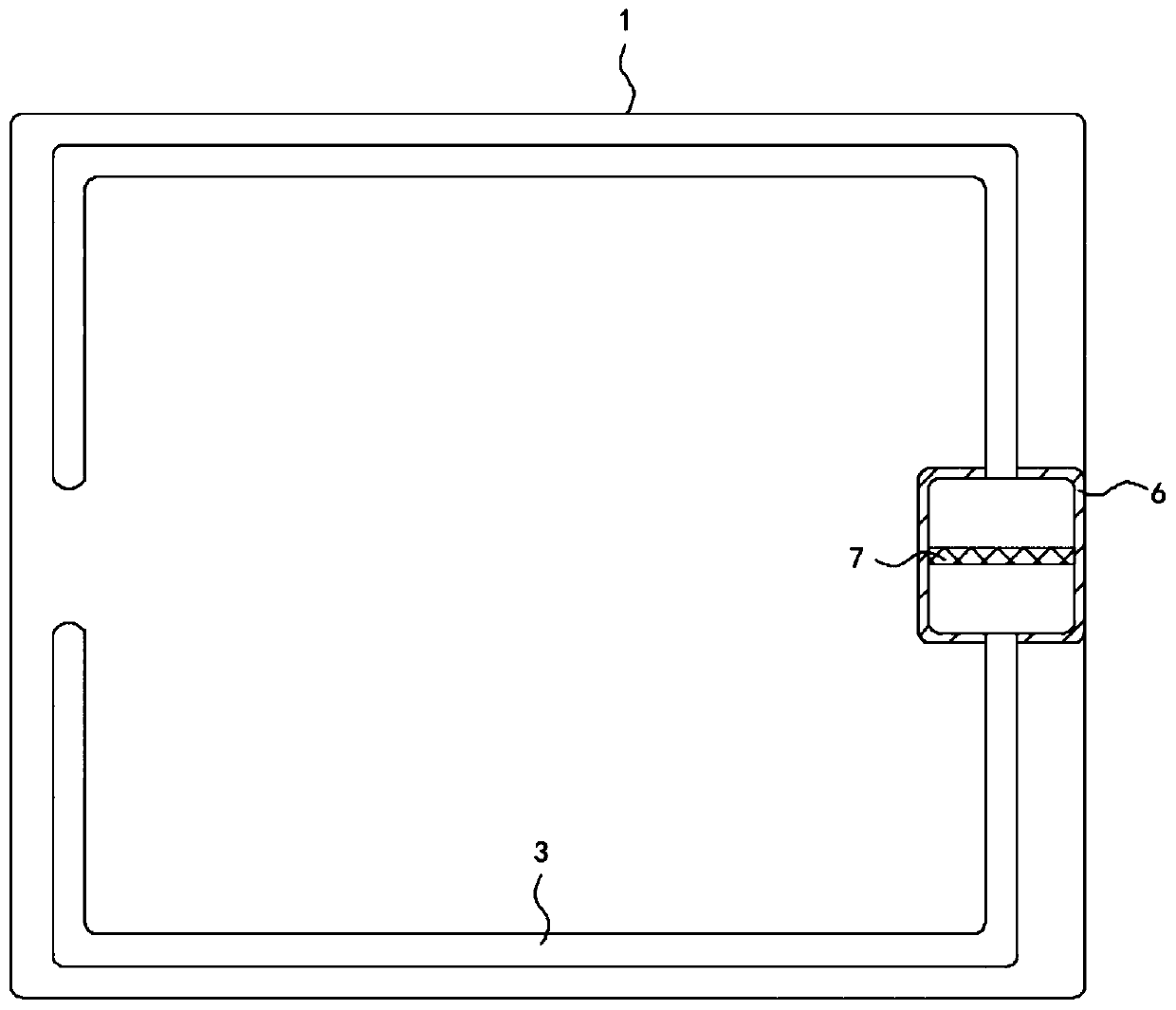
[0022] Such as Figure 1-5 As shown, a high-efficiency aerated sewage treatment tank with defoaming function includes a tank body 1 and an air supply pump 2. Two horizontally arranged semi-circular shunt pipes 3 are fixedly connected to the side wall of the tank body 1, which is worth It should be mentioned that a spoiler 11 is provided in the semi-annular shunt pipe 3, and the spoiler 11 is arranged in a spiral shape. The spoiler 11 can make part of the oxygen in the air dissolve into the small air when flowing in the semi-annular shunt pipe 3. In the liquid droplets, the dissolved oxygen rate is increased, and one end of the two semi-annular shunt pipes 3 is connected to the air supply pump 2, and the lower side wall of the semi-annular shunt pipe 3 is fixedly connected to a plurality of equidistantly arranged defoaming pipes 4 The lower end of the defoaming pipe 4 is tapered and extends to the water surface in the pool body 1, and the inner wall of the defoaming pipe 4 is f...

Embodiment 2

[0026] Such as Image 6 As shown, the difference between this embodiment and Embodiment 1 is that a strip baffle 12 is provided above the aeration tube 8, and the strip baffle 12 is fixedly connected with the aeration tube 8 through a support rod. The width of 12 is equal to the diameter of aeration pipe 8.

[0027] In this embodiment, the air flows out from the aeration hole 10 into the pool body 1, and floats upward under the action of buoyancy. According to the phenomenon of Karman vortex street, when the steady incoming flow bypasses some objects under certain conditions, the two sides of the object will The side will periodically fall out of the opposite direction of rotation and arranged in a regular double-row linear vortex, then in the process of floating upward, the air needs to bypass the bar-shaped baffle 12 to form a double-row vortex in the opposite direction of rotation and arranged in a regular pattern. Alignment vortex, during the floating process, the air has...


PUM


Abstract

The invention belongs to the field of sewage treatment facilities, and particularly relates to an efficient aeration sewage treatment pool with bubble eliminating function. The efficient aeration sewage treatment pool comprises a pool body and a gas supply pump, wherein the peripheral side wall of the pool body is fixedly connected with two semi-annular flow splitting pipes horizontally arranged,one ends of the two semi-annular flow splitting pipes are communicated with the gas supply pump, a plurality of bubble eliminating pipes distributed at equal intervals are fixedly communicated with the lower side walls of the semi-annular flow splitting pipes, the lower ends of the bubble eliminating pipes are conical and extend to the water surface in the pool body, the inner side wall of the bubble eliminating pipe is fixedly connected with a plurality of obliquely downward bubble poking needles, the two semi-annular flow splitting pipes are fixed and communicated through a mixing box, the outflow ends of the two semi-annular flow splitting pipes are right opposite to each other, and the inner side wall of the mixing box is fixedly connected with a condensate net plate. According to theinvention, large gas bubbles can be punctured by the bubble eliminating pipes, and small gas bubbles are sucked into the bubble eliminating pipes and are subjected to contact fusion with air, so thatthe oxygen dissolving efficiency is improved, and the activity of aerobic bacteria is effectively improved.

Description

technical field [0001] The invention belongs to the field of sewage treatment facilities, in particular to a high-efficiency aeration sewage treatment pool with defoaming function. Background technique [0002] In sewage treatment, it is usually necessary to decompose organic matter in sewage by means of microbial degradation, and aerobic bacteria pools and anaerobic bacteria pools need to be configured; for aerobic bacteria pools, in order to improve the activity of aerobic bacteria, ensure Due to the effect of biochemical reactions, it is necessary to set up an aeration system in the pool to continuously provide a large amount of oxygen to the pool. [0003] The water surface of the sewage treatment tank usually produces a lot of foam, and the foam contains a lot of impurities. Under the push of the aeration wave, the foam gradually moves and accumulates around the sewage tank. If the foam is not removed in time, the foam will easily flow out of the pool. Overflow will ca...

Claims


Application Information

Patent Timeline
IPC IPC(8): C02F7/00C02F3/02C02F3/20B01D19/02C02F101/30
CPCC02F7/00C02F3/02C02F3/201B01D19/02C02F2101/30Y02W10/10
Inventor 王金鑫闫慧强
Owner 广州中晟水务环保科技有限公司
Learn More