Vehicle energy management method for electric vehicle power system, and vehicle

A vehicle energy management and power system technology, which is applied to the vehicle energy management method of the electric vehicle power system and the field of vehicles, can solve the problem of low instantaneous output power, affecting durability, and the inability to achieve short-term, high-power electric energy output, etc. problems, to achieve the effect of prolonging the service life, ensuring power and economy

Active Publication Date: 2020-02-21
CHINA FIRST AUTOMOBILE
View PDF8 Cites 8 Cited by
  • Summary
  • Abstract
  • Description
  • Claims
  • Application Information

AI Technical Summary

Problems solved by technology

[0004]The disadvantages of the existing technical solutions are: firstly, the output power of the fuel cell is greatly affected by the working temperature, the low temperature time limit power or no output power, and the high temperature time limit power or not Output power, only in a certain temperature range can the normal output power, thus unable to meet the power output under extreme working conditions such as low temperature and high temperature
Secondly, the dynamic power response of the fuel cell is slow, and it is impossible to achieve short-term, high-power electric energy output, that is, the instantaneous output power is low, so it cannot meet the power output of the vehicle under extreme working conditions such as starting, climbing, and rapid acceleration. need
Furthermore, the fuel cell itself can only generate energy and cannot store energy. Therefore, this solution cannot realize the energy recovery of the whole vehicle when the vehicle is coasting or braking.
In addition, the fuel cell may need to be shut down when the power demand of the vehicle is low or deceleration, and the frequent start and stop of the fuel cell will shorten the life of the fuel cell and affect the durability

Method used


Image

  • Vehicle energy management method for electric vehicle power system, and vehicle
  • Vehicle energy management method for electric vehicle power system, and vehicle
  • Vehicle energy management method for electric vehicle power system, and vehicle

Examples


Embodiment 1

[0051] figure 1 It is a schematic flowchart of a vehicle energy management method for an electric vehicle power system provided by Embodiment 1 of the present invention. This embodiment is applicable to electric vehicles using a composite power supply scheme of a flywheel battery and a fuel cell, and the battery is selected based on the temperature of the fuel cell. mode, so as to realize the situation of vehicle energy management; this method can be executed by the vehicle controller, and the vehicle controller can be realized by hardware and / or software, and generally integrated in the electric vehicle applying the vehicle energy management method on the car.

[0052] It can be understood that, according to the characteristics of the fuel cell, firstly, the output power of the fuel cell is greatly affected by the operating temperature, and cannot meet the power output under extreme working conditions such as low temperature and high temperature. Secondly, the dynamic power ...

Embodiment 2

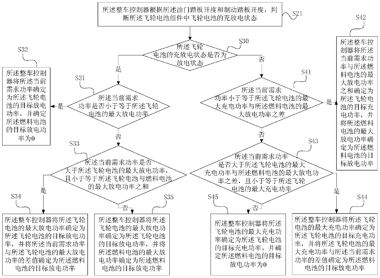
[0092] figure 2 It is a schematic flowchart of a vehicle energy management method for a power system of an electric vehicle provided in Embodiment 2 of the present invention. This embodiment is further optimized on the basis of Embodiment 1. In this embodiment, the vehicle controller allocates power to the battery in the battery usage mode according to the current demand power, and the specific optimization is: when the battery usage mode is the flywheel battery assembly priority mode, the The vehicle controller performs the first charge and discharge power distribution on the flywheel battery in the flywheel battery assembly according to the current demand power combined with the first power distribution strategy, and performs the first discharge power distribution on the fuel cells in the fuel cell assembly ; When the battery usage mode is the fuel cell assembly priority mode, the vehicle controller performs a power distribution for the flywheel battery in the flywheel batt...

Embodiment 3

[0155] Figure 5 It is a schematic structural diagram of a vehicle provided by Embodiment 3 of the present invention. like Figure 5 As shown, the vehicle includes: a vehicle controller 301 , a flywheel battery assembly 302 , a fuel cell assembly 303 , an accelerator pedal 304 , a brake pedal 305 , a charging assembly 306 , a motor assembly 307 and a memory 308 .

[0156] Among them, the vehicle controller 301 is respectively connected with the flywheel battery assembly 302, the fuel cell assembly 303, the accelerator pedal 304, the brake pedal 305, the charging assembly 306, the motor assembly 307 and the memory 308, and is used to collect the working conditions of other components. , and send corresponding control commands to other components according to the working conditions, so as to complete the management and distribution of vehicle energy.

[0157] The flywheel battery assembly 302 is connected to the vehicle controller 301, the fuel cell assembly 303 and the motor ...


PUM


Abstract

The embodiment of the invention discloses a vehicle energy management method for an electric vehicle power system, and a vehicle. The method comprises the following steps that a vehicle control unit receives a current fuel battery temperature fed from a fuel battery component; the vehicle control unit compares the current fuel battery temperature with a preset temperature threshold value, and determines a battery use mode according to a comparison result; and the vehicle control unit determines the current demanded power of the vehicle according to the obtained current working condition of thevehicle, and carries out power distribution on a battery under the battery use mode according to the current demanded power. By use of the above scheme of the embodiment of the invention, defects generated since an electric vehicle adopts a single fuel battery to supply electricity are eliminated, the power demands of the vehicle under ultimate working conditions, including low-temperature startup, a high temperature and the like, can be effectively guaranteed, effective protection is provided for the fuel battery while the dynamic property and the economic efficiency of the vehicle are guaranteed, and the service life of the fuel battery is prolonged.

Description

technical field [0001] Embodiments of the present invention relate to the technical field of electric vehicles, and in particular to a vehicle energy management method for a power system of an electric vehicle and a vehicle. Background technique [0002] Fuel cells have the advantages of high energy density, zero pollution emissions, high efficiency, low noise, etc., resulting in fuel cell electric vehicles. [0003] The power supply system is an important part of the power system of electric vehicles. At present, the power supply system of fuel cell electric vehicles mostly adopts the fuel cell, a single type of battery-powered solution. [0004] The disadvantages of the existing technical solutions are: firstly, the output power of the fuel cell is greatly affected by the working temperature, the low-temperature time-limited power may or may not output power, and the high-temperature time-limited power may or may not output power, and the normal output power is only within...

Claims


Application Information

Patent Timeline
Patent Type & Authority Applications(China)
IPC IPC(8): B60L50/70B60L58/32B60L50/30
CPCB60L50/70B60L58/32B60L50/30Y02T90/40Y02T10/70
Inventor 刘力源
Owner CHINA FIRST AUTOMOBILE
Why Eureka
Try Eureka