
Booster of implantable medical device and implantable medical system

An implantable medical and medical device technology, applied in the direction of sensors, medical science, catheters, etc., can solve the problems of high cost of use, cumbersome implantation process, excessive force or too small user, etc., and achieve compact structure and compact overall structure , the effect of low cost of use

Active Publication Date: 2020-02-21
江西司托迈医疗科技有限公司
View PDF5 Cites 2 Cited by
  • Summary
  • Abstract
  • Description
  • Claims
  • Application Information

AI Technical Summary

Problems solved by technology

[0003] For the continuous blood glucose monitoring system CGM, the implant tool for implanting the blood glucose test sensor is one of the indispensable devices. The implant tool in the prior art often has excessive force due to human factors during use. or is too small to cause user discomfort
[0004] CN109938785A discloses an implant tool, although it obtains a uniform ejection force through the ejection spring to solve the above problems, but when triggering the ejection, it is necessary to press the button at the proximal end of the implant tool, which makes the implantation process cumbersome And the structure of the implant tool becomes complicated
When the first restraint arm constrains the second restraint arm, the needle holder is clamped by the implant tool. After the needle holder implants the needle, the second restraint arm cannot return to the inside of the first restraint arm, and the needle holder cannot return. Implants cannot be reused
[0006] Moreover, the implant tool cannot separate and recycle the used puncture needle, which also results in the implant tool being unable to be reused, and the use cost is high

Method used


Image

  • Booster of implantable medical device and implantable medical system
  • Booster of implantable medical device and implantable medical system
  • Booster of implantable medical device and implantable medical system

Examples


Embodiment Construction

[0077] Exemplary embodiments of the present invention are described below with reference to the accompanying drawings. It should be understood that these specific descriptions are only used to teach those skilled in the art how to implement the present invention, but are not intended to exhaust all possible ways of the present invention, nor are they intended to limit the scope of the present invention.

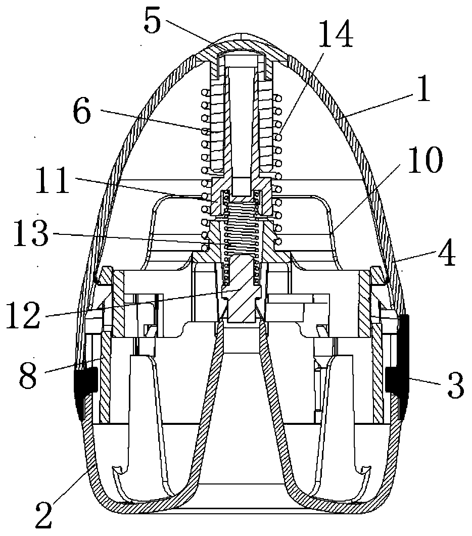
[0078] The present disclosure provides a booster for an implantable medical device and an implantable medical system. The booster is used to push the implanted medical device under the skin of the living body, and the implanted medical system includes the booster and the implanted medical device. The implantable medical device may include sensors, perfusion devices, etc., and the booster includes a pusher, such as a puncture needle assembly including a puncture needle and a needle seat. The implantable medical device is installed on the pusher and enters into the skin along w...


PUM


Abstract

The invention provides a booster of an implantable medical device and an implantable medical system. The booster is used for installing the implantable medical device and a push member and ejecting the push member, wherein the booster includes a push member mounting part, the push member mounting part includes at least two hook arms, and push member installation space for installing the push member is formed in the radial inner side of the at least two hook arms; the hook arms extends substantially in the ejection direction of the push member so as to form a cantilever structure which adopts the distal ends of the hook arms as free ends; and when a far-to-near force is applied to the distal ends of the hook arms, the distal ends of the hook arms move radially and outwards so as to make thepush member installation space larger, and the push member can be released from the push member installation space or be loaded into the push member installation space. When implantation is completed, the booster can be used for releasing the push member and installing a new push member, and the booster is not a disposable product, but can be reused, so that the application cost is low.

Description

technical field [0001] The invention relates to the technical field of medical devices, and in particular to a booster for an implanted medical device and an implanted medical system. Background technique [0002] There are two main methods of blood sugar testing: one is to puncture a finger to collect fingertip blood, and use the blood glucose test strips for testing to cooperate with the blood glucose meter to collect discrete blood glucose values; the other is the dynamic blood glucose monitoring system CGM, which implants a blood sugar sensor under the skin, the enzyme on the sensor reacts with the subcutaneous tissue fluid to detect the blood sugar level, and cooperates with the transmitter to send the blood sugar level to the terminal. This method can collect continuous blood sugar levels. [0003] For the continuous blood glucose monitoring system CGM, the implant tool for implanting the blood glucose test sensor is one of the indispensable devices. The implant tool i...

Claims


Application Information

Patent Timeline
Patent Type & Authority Applications(China)
IPC IPC(8): A61B5/1486
CPCA61B5/14865A61B5/14532
Inventor 李东华樊建锋刘学宇龙小燕
Owner 江西司托迈医疗科技有限公司
Learn More