Transformer primary side transient signal measurement method and system based on L2 deconvolution
A technology of transient signal and transformer, applied in the direction of instruments, measuring electricity, measuring devices, etc., can solve the problems of unreliable test results and so on
- Summary
- Abstract
- Description
- Claims
- Application Information
AI Technical Summary
Problems solved by technology
Method used
Image
Examples
Embodiment 1
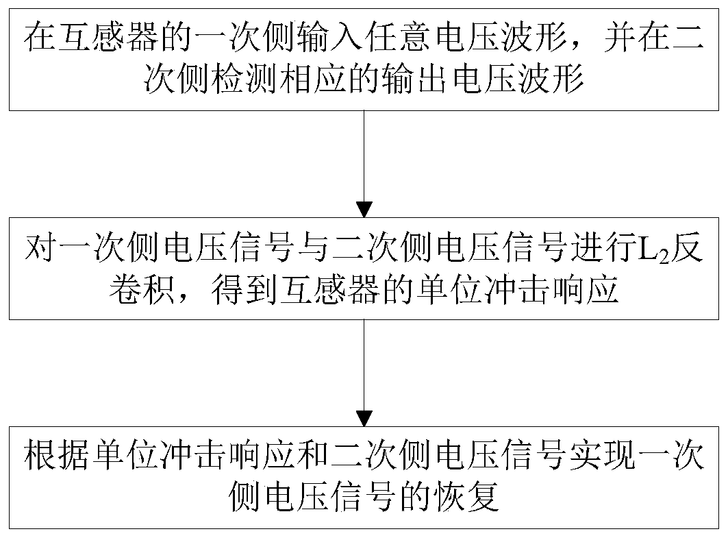
[0074] Based on L 2 Deconvolution transformer primary side transient signal measurement method, such as figure 1 As shown, the method includes the following steps:
[0075] In step S1, an arbitrary voltage waveform is input on the primary side of the transformer, and a corresponding output voltage waveform is detected on the secondary side.
[0076] Step S2, performing L on the primary side voltage signal and the secondary side voltage signal 2 Deconvolute to obtain the unit impulse response of the transformer.
[0077] In this embodiment, the specific implementation process of step S2 is as follows:
[0078] Step S21, let x[n], y[n], h[n] and e[n] denote the transformer primary side voltage signal, secondary side voltage signal, unit impulse response signal and error signal respectively, and the data lengths are respectively for M x , M y , M h and M e , then the following relationship is obtained:
[0079] y[n]=x[n]*h[n]+e[n] (1)
[0080] m h = M y -M x +1 (2) ...
Embodiment 2
[0104] Based on the above-mentioned embodiment 1, this embodiment proposes based on L 2 Deconvolution transformer primary side transient signal measurement system, the system includes: data acquisition module, used to obtain the transformer primary side input voltage signal and secondary side output voltage signal; unit impulse response calculation module, used for The transformer primary side input voltage signal and secondary side output voltage signal obtained by the data acquisition module are L 2 Deconvolution to obtain the unit impulse response of the transformer; the primary side transient signal recovery module realizes the primary side voltage signal according to the unit impulse response obtained by the unit impulse response calculation module and the transformer secondary side output voltage signal obtained by the data acquisition module recovery.
[0105] Specifically, in this embodiment, the unit impulse response calculation module is specifically configured to i...
Embodiment 3
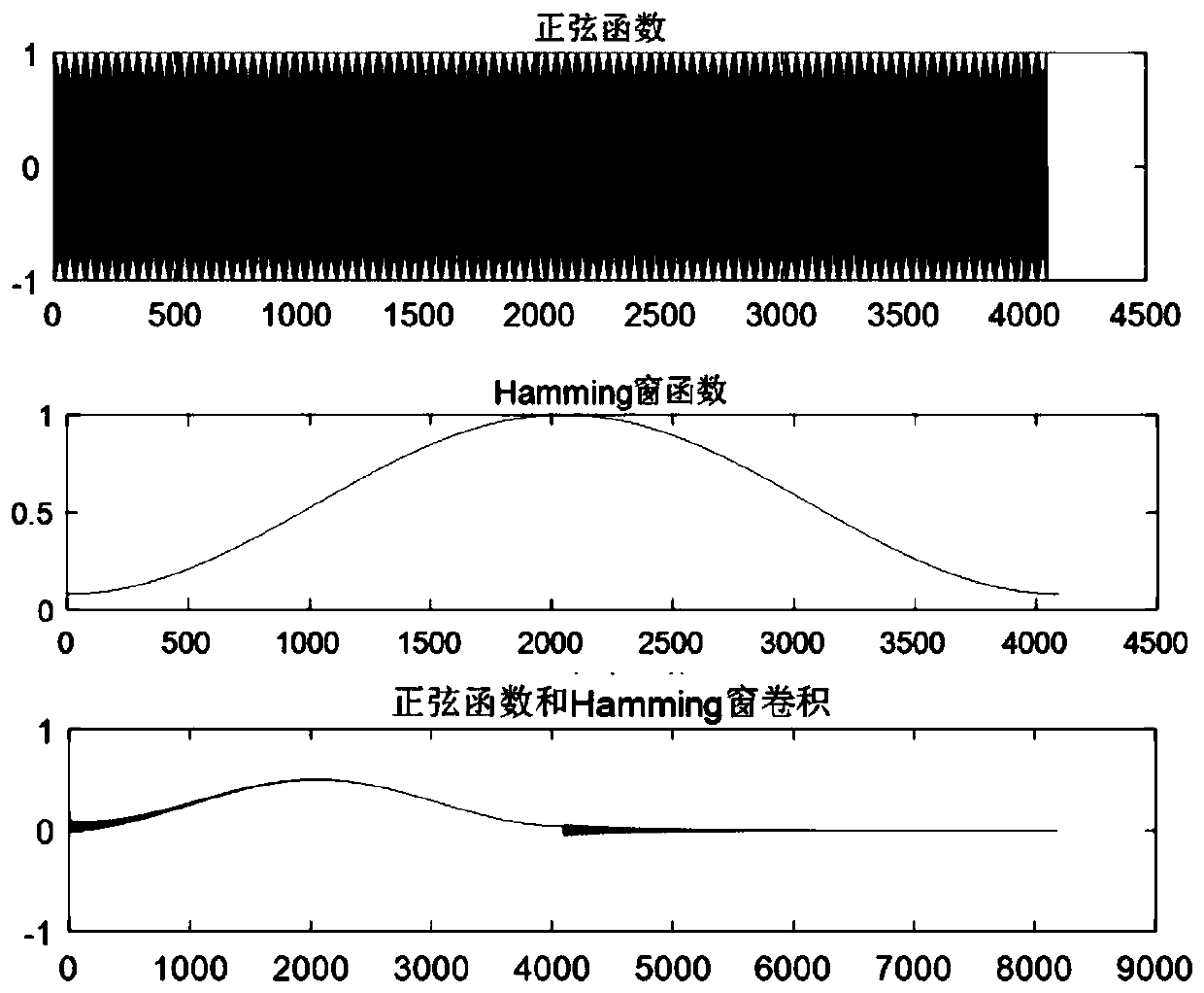
[0108] This embodiment is based on MATLAB to carry out simulation experiments on the method and system proposed in the above-mentioned embodiment 1 and embodiment 2, specifically including:
[0109] A. Use MATLAB to preset a sine wave as the input, a Hamming window function as the system unit impulse response, and convolute them to obtain the output, such as figure 2 shown;
[0110] B. Perform L on input and output 2 Deconvolution, calculate the unit impulse response of the system;
[0111] C. Perform L on the calculated unit impulse response and output 2 Deconvolution, calculate the input;
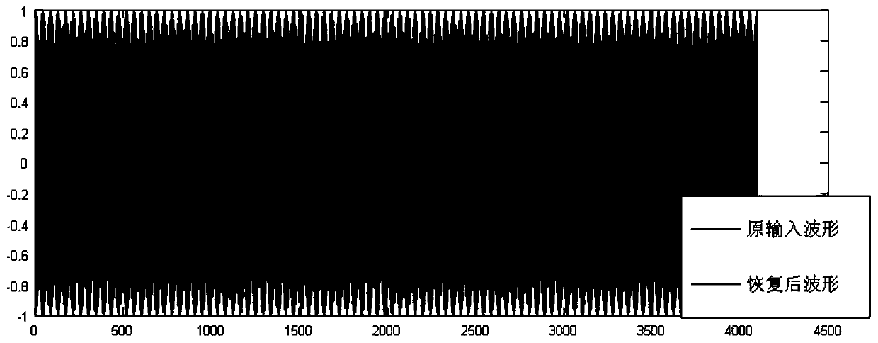
[0112] D. If image 3 As shown, comparing the error between the actual input and the calculated input, after calculation, the relative error between the two is 1.16e-5, and the restoration effect is very good.
PUM
 Abstract
Description
Claims
Application Information
 - R&D
- Intellectual Property
- Life Sciences
- Materials
- Tech Scout
- Unparalleled Data Quality
- Higher Quality Content
- 60% Fewer Hallucinations
Browse by: Latest US Patents, China's latest patents, Technical Efficacy Thesaurus, Application Domain, Technology Topic, Popular Technical Reports.
© 2025 PatSnap. All rights reserved.Legal|Privacy policy|Modern Slavery Act Transparency Statement|Sitemap|About US| Contact US: help@patsnap.com


