Shutter-type vacuum furnace observation window

A technology of observation window and vacuum furnace, which is applied in the field of flicker-free observation window structure and its protection, which can solve the problems of difficult maintenance and repair operations, increased costs, and large volume of observation windows, so as to reduce observation fatigue and prolong use The effect of long life and large aperture

Inactive Publication Date: 2020-02-14
宁波鑫利成真空科技有限公司
View PDF1 Cites 0 Cited by
  • Summary
  • Abstract
  • Description
  • Claims
  • Application Information

AI Technical Summary

Problems solved by technology

[0004] 1. The blade rotation mechanism is complex and expensive
This method uses the method of a built-in motor in the vacuum chamber to drive the blades to rotate at high speed. Although the problem of vacuum dynamic sealing of the transmission shaft caused by the external motor is avoided, the cost is also greatly increased due to the use of a vacuum motor.
[0005] 2. The observation window is large
Due to the space required for the rotation of the blades, the overall space required for the observation window is much larger than the optical path required for direct observation, and the effective use area is often only 1 / 4 or even less
This makes the arrangement of observation windows take up a large amount of space, and it is often necessary to consider the possible interference with other components, which seriously restricts the choice of arrangement of observation windows
Moreover, the overall weight of the observation window is large, and maintenance and repair operations are difficult
[0006] 3. Since the motor speed drives the blade slit to form the shutter, stroboscopic phenomenon is inevitable
When the operator directly observes, the strobe will cause visual fatigue, which is very unfavorable to the operator who works for a long time
When using a camera for remote monitoring, the speed of the slit shutter is different from the scanning frequency of the camera, often resulting in alternating dark areas on the remote monitoring screen

Method used


Image

  • Shutter-type vacuum furnace observation window

Examples


Embodiment Construction

[0031] In order to make the object, technical solution and advantages of the present invention clearer, the present invention will be further described in detail below in conjunction with the accompanying drawings.

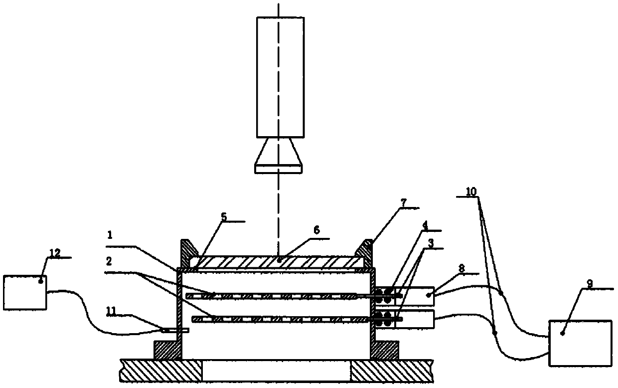
[0032] As shown in the figure, a shutter-type vacuum furnace observation window includes an observation window cavity 1 that can be installed to the observation port of the vacuum furnace, and a shutter-type blade 2 placed in the observation window cavity, which is connected to each blade and connected to an external drive system The driving link mechanism 3, the driving rod dynamic sealing mechanism 4 to ensure vacuum, the vacuum sealing ring 5 for the observation window glass sealing, the observation window glass lens 6, the observation window cover 7 that presses the observation window glass, and is placed on the observation window Outside the cavity, the drive rod actuator 8 of the drive mechanism, the control and adjustment unit 9 of the actuator and the elect...


PUM


Abstract

The invention relates to a shutter-type vacuum furnace observation window. The shutter-type vacuum furnace observation window comprises an observation window cavity which can be arranged on a vacuum furnace observation opening, shutter-type blades which are placed in the observation window cavity, driving connection rod mechanisms which are connected to the blades and are connected to an externaldriving system, driving rod movable sealing mechanisms for ensuring vacuum, a vacuum sealing ring used for sealing observation window glass, an observation window glass lens, an observation window cover for compacting the observation window glass, driving rod execution mechanisms which are placed out of the observation window cavity and are connected to a driving mechanism through movable sealingand controlling and adjusting units and electric connection cables of the execution mechanisms; the shutter-type blades with variable frequencies are used, so that the luminous flux and the exposure frequency can be adjusted at will on the premise of ensuring sufficient luminous flux, and a bright field of view and matching camera scanning are realized, and the effect of eradicating stroboflash isrealized, which is of great benefit to both human eyes and cameras; and by adopting the design, the size of the observation window can be greatly reduced, and the observation window is arranged on avacuum furnace conveniently.

Description

technical field [0001] The invention relates to a vacuum furnace observation window structure and protection method, in particular to a flicker-free observation window structure and protection method that can work continuously for a long time and prevent volatile matter from adhering to the lens. Background technique [0002] In the process of smelting or evaporation processing in the vacuum furnace, the staff often need to observe the materials and working status in the furnace, so as to grasp the situation in the furnace at any time, control and adjust the process and avoid accidents. This is especially important for electron beam melting furnaces and vacuum coating equipment, but various evaporating substances in the furnace are often evaporated and adhered to the lens of the observation window, forming a block, which seriously hinders the operation of the staff. Therefore, a reliable and stable observation window that can protect the observation window from being blocked...

Claims


Application Information

Patent Timeline
Patent Type & Authority Applications(China)
IPC IPC(8): F27D21/02
CPCF27D21/02
Inventor 赵文天
Owner 宁波鑫利成真空科技有限公司
Why Eureka
Try Eureka