
Fan and method for replacing filter of fan

A filter and fan technology, used in machines/engines, components of pumping devices for elastic fluids, non-variable-capacity pumps, etc. Use and other issues to achieve the effect of reducing the cost of use and reducing the overall volume

Pending Publication Date: 2020-02-14
应辉
View PDF0 Cites 5 Cited by
  • Summary
  • Abstract
  • Description
  • Claims
  • Application Information

AI Technical Summary

Problems solved by technology

[0006] (1) Since the annular nozzle and the fan motor with the largest total volume of the bladeless fan must be arranged at different heights in the direction of gravity, it is difficult to reduce the overall height of the bladeless fan, which greatly limits the usage scenarios of the bladeless fan
[0007] (2) The middle of the annular nozzle is hollow, and this area is not fully utilized, resulting in a waste of the overall volume of the fan, and an increase in the cost of product transportation and product storage
[0008] (3) Since the position of the air inlet of the fan motor is lower, it is easier to inhale the dust on the ground when inhaling, which increases the load on the filter screen and requires more frequent replacement of the filter screen, which significantly increases the size of the bladeless fan. cost of use
The filter screen is sealed between the downstream three-dimensional sealing strip and the mesh liner. The cost of the three-dimensional sealing strip is extremely high, and the sealing effect is poor after long-term use
[0010] (5) When replacing the filter screen, it is necessary to disassemble the two shells and replace the filter screen respectively and then install them back. The process is cumbersome and the user-friendly experience is poor
[0011] (6) It is difficult to add other functional modules to the product, and the scalability is poor

Method used


Image

  • Fan and method for replacing filter of fan
  • Fan and method for replacing filter of fan
  • Fan and method for replacing filter of fan

Examples


Embodiment Construction

[0092] Example embodiments will now be described more fully with reference to the accompanying drawings. However, the example embodiment can be implemented in various forms, and should not be construed as being limited to the embodiment set forth herein. On the contrary, these embodiments are provided so that the present invention will be comprehensive and complete, and will fully convey the concept of example embodiments to those skilled in the art. The same reference numerals in the figures denote the same or similar structures, and thus their repeated description will be omitted.

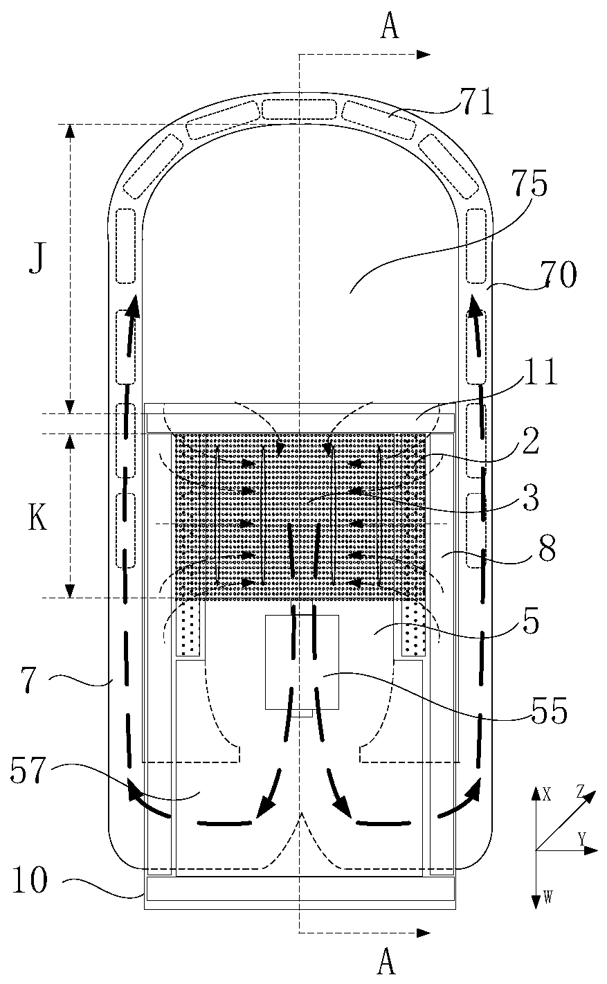
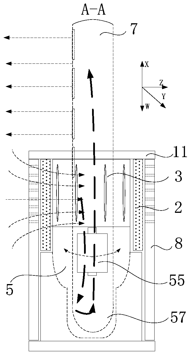
[0093] figure 2 It is a schematic diagram of the internal air duct of the fan of the present invention. image 3 Yes figure 2 A cross-sectional view in the A-A direction. Such as figure 2 with 3 As shown, the fan of the present invention includes a body 10 for generating an air flow and a nozzle 7 for spraying the air flow. Wherein, the body 10 at least includes a top cover 11, a filter 2, an a...


PUM


Abstract

The invention provides a fan and a method for replacing a filter of the fan. The fan comprises a body part and a nozzle. The body part comprises an air inlet, an air outlet, the detachable filter anda fan motor assembly used for generating airflow. The nozzle is connected with the air outlet and used for receiving the airflow from the body part and ejecting airflow which then enters the nozzle along with the received airflow. An air outlet of the fan motor assembly is connected with two guide airways, and the guide airways communicate with openings on the two sides of the body part respectively; an accommodating space is defined between a first side surface of the body part and a first side surface of a nozzle body, the accommodating space is provided with at least one replacing channel for the filter to enter or leave the accommodating space, and the extending direction of the replacing channel is perpendicular to a second direction; and the filter has a first stroke for entering orleaving the accommodating space from the body part in the second direction and a second stroke for entering or leaving the accommodating space from the replacing channel.

Description

Technical field [0001] The present invention relates to the field of air conditioning equipment, and in particular to a fan and a method for replacing a filter with the fan. Background technique [0002] With the continuous improvement of the standard of living and technology, the people's requirements for the quality of life are increasing, and indoor air quality has become an important issue of concern to people. Especially with the emergence of smog and PM2.5 in recent years, people's demand for air purifiers is also increasing. [0003] Air purifiers are small household appliances used to purify indoor air, mainly to solve indoor air pollution problems caused by repairs or other reasons. Because the release of pollutants in indoor air is persistent and uncertain, the use of air purifiers to purify indoor air is an internationally recognized method to improve indoor air quality. There are many different technologies and media in air purifiers that enable it to provide users wi...

Claims


Application Information

Patent Timeline
IPC IPC(8): F04F5/16F04F5/44F04F5/46F04D25/08F04D29/70F04D29/60F04D29/40
CPCF04F5/16F04F5/44F04F5/46F04D25/08F04D29/703F04D29/601F04D29/403Y02B30/70
Inventor 应辉
Owner 应辉
Learn More