Connection of elements in motor vehicles

A technology for motor vehicles and components, which is applied in the direction of connection between motor vehicles, vehicle parts, and superstructure subassemblies, and can solve problems such as high cost, restrictions, and difficulties in bonding components to each other, and achieve the effect of easy handling

Active Publication Date: 2020-02-11
SIKA TECH AG
View PDF7 Cites 0 Cited by
  • Summary
  • Abstract
  • Description
  • Claims
  • Application Information

AI Technical Summary

Problems solved by technology

However, such known methods have the disadvantage that the handling of the components to be bonded and the application of the adhesive is costly on the one hand and restrictive on the other hand
It is difficult, for example, to bond mutually nested elements to one another using this method.

Method used


Image

  • Connection of elements in motor vehicles
  • Connection of elements in motor vehicles
  • Connection of elements in motor vehicles

Examples


Embodiment Construction

[0073] exist figure 1 A body 10 of a motor vehicle is schematically shown in FIG. Body 10 here has a number of different structural parts, such as pillars 14 and struts 12 . These and other structures of the body 10 must be connected to one another by suitable means. In this case, in particular profiles, castings and plate-shaped elements can be connected to one another.

[0074] exist figure 2 A part of the first element 1 is schematically shown in . The first element 1 here has a groove 3 on its surface. At the same time, the surface of the first element 1 forms a shoulder 6 beside the recess 3 . The groove 3 here has a groove length 16 .

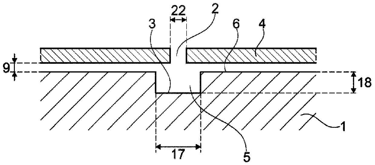
[0075] exist image 3 A partial cross-section of the first element 1 and the second element 4 is schematically shown in . The first element 1 again has a recess 3 formed on the surface of the first element 1 . The groove 3 here has a groove width 17 and a groove depth 18 . The cross section of the groove 3 is rectangular in thi...


PUM

PropertyMeasurementUnit
depthaaaaaaaaaa
lengthaaaaaaaaaa
diameteraaaaaaaaaa

Abstract

A system of connected elements for a motor vehicle comprises: a first element which has at least one depression on a surface; a second element which is arranged on the first element in such a manner that a surface of the second element and the depression of the first element form a cavity; a filling opening which forms an access to the cavity; and an adhesive which at least partially fills the cavity and thereby adhesively bonds the first element to the second element.

Description

technical field [0001] The invention relates to a system for connecting components of a motor vehicle and a method for connecting components in a motor vehicle. Background technique [0002] For joining, elements such as extruded profiles, castings or sheets are often glued to one another. At the same time, an adhesive is used which is applied as an adhesive strip to the first component, wherein the second component to be bonded is then applied to this adhesive strip in order to bond the two components. However, such known methods have the disadvantage that the handling of the components to be bonded and the application of the adhesive is expensive on the one hand and restrictive on the other hand. It is thus difficult, for example, to glue mutually nested elements together using this method. This is so because the adhesive tape applied to the first element can be scraped off during assembly of the second element and is therefore no longer in the desired position for gluin...

Claims


Application Information

Patent Timeline
Patent Type & Authority Applications(China)
IPC IPC(8): B62D27/06B62D65/02B62D27/02
CPCB62D27/026B62D27/06B62D65/02B29C65/542B62D29/001B62D29/04B29C66/022B29C65/4835B29C66/30325B29C66/43B29C66/301B29C66/919B29C66/21B29C65/485
Inventor P·韦伯
Owner SIKA TECH AG
Why Eureka
Try Eureka