Post-type multi-directional wire collector
What is Al technical title?
Al technical title is built by PatSnap Al team. It summarizes the technical point description of the patent document.
A wire and column technology, applied in the field of wire collectors, can solve the problems of unstable conduction, easy loosening, and few lines, and achieve the effects of simple manufacture, beautiful structure and simple implementation.
Active Publication Date: 2016-08-24
江苏瑞特钢化玻璃制品有限公司
View PDF4 Cites 0 Cited by
Summary
Abstract
Description
Claims
Application Information
AI Technical Summary
This helps you quickly interpret patents by identifying the three key elements:
Problems solved by technology
Method used
Benefits of technology
Problems solved by technology
[0003] The purpose of the present invention is to overcome the shortcomings of the current known wire collection equipment, such as single wire collection direction, relatively few lines, unstable conduction, easy to loosen, etc., and provide the public with a unique post-mounted multi-directional wire collection device
Method used
Image
Click on the blue label to locate the original text in one second.
Reading with bidirectional positioning of images and text.
Examples
Embodiment Construction
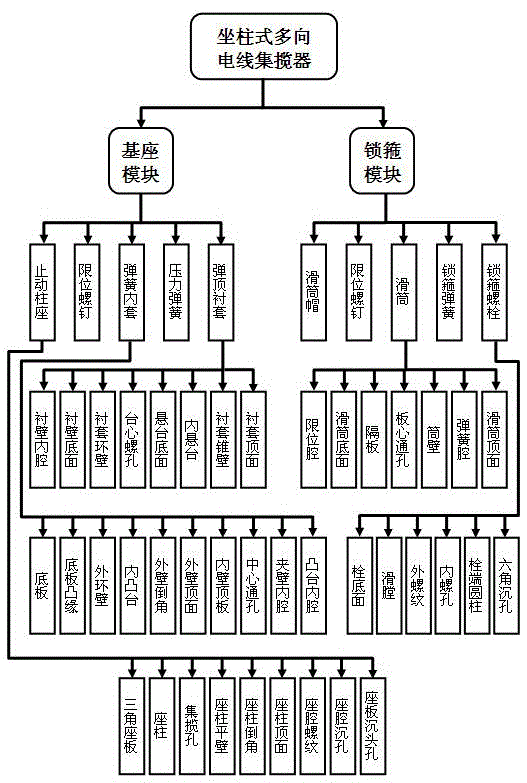
[0035] As a technical proposal for product manufacturing, the present invention can implement the proposal through the organic combination of corresponding organizational structures. The organizational structure of the product of an embodiment of the present invention is as figure 1 shown.
[0036] figure 1 Among them, the product is composed of two modules, the base and the lock hoop. The base module is composed of five parts: the stop post, the limit screw, the spring inner sleeve, the pressure spring, and the top bushing. The lock hoop module is composed of the slide It is composed of five parts: cylinder cap, limit screw, sliding cylinder, lock spring and lock bolt.
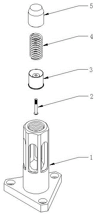
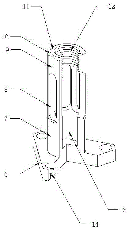
[0037] In the embodiment, each part has its own unique shape. The shape of the parts belonging to the base module is as follows: figure 2 shown.
[0038] figure 2 Among them, the parts arranged in the order of numbers are: stop column seat part (1), limit screw part (2), spring inner sleeve part (3), ...
PUM
Abstract
The invention relates to electric wire winding equipment, in particular to an electric wire winder, which has a fixed-post structure, can almost adapt to any external direction and is used for tightly connecting bundles of electric wires and statically and stably conducting current. The electric wire winder consists of a base module and a locking hoop module, and comprises dozens of parts such as a retaining post seat, a limiting screw, a spring inner sleeve, an elastic jacking bush, a sliding barrel cap, a sliding barrel, a locking hoop spring and a locking hoop bolt. The defects of single wire winding direction, excessively small wire winding quantity, lead looseness, unstable current conducting performance and the like in a current well-known electric wire winder are overcome, and a unique fixed-post multi-direction electric wire winding device is provided for people. Apart from the function of conducting current among a plurality of strands of electric wires of well-known electric wire winding equipment, the electric wire winder further has the beneficial effects of extensive connection, compact connection, static and stable conduction, wide use and the like. Moreover, the electric wire winder is easy to implement, and is easy to manufacture. A formed product is attractive, elegant, firm and durable, and has a wide market space and high practical value and economical added value.
Description
technical field [0001] The present invention relates to a wire collection device, in particular to a wire collection device which adopts a column structure, can adapt to almost any external direction, fastens and connects multiple wires and conducts electric current stably. Background technique [0002] Wire collecting equipment, or "wire collecting device", refers to a cylindrical device used to connect multiple wires to each other. Its main function is to make multiple currents gather together to form a current, or to make a Shared current is evenly distributed to multiple consumers. Although the current known wire collectors can basically meet the needs of general current collection and conduction, they often have a single direction of wire collection, too few wires, loose wires, unstable conductivity, and easy loosening. Defects such as detachment, thereby affecting the use function, application range and socio-economic value of the known electric wire collection equipm...
Claims
Application Information
Patent Timeline
Application Date:The date an application was filed.
Publication Date:The date a patent or application was officially published.
First Publication Date:The earliest publication date of a patent with the same application number.
Issue Date:Publication date of the patent grant document.
PCT Entry Date:The Entry date of PCT National Phase.
Estimated Expiry Date:The statutory expiry date of a patent right according to the Patent Law, and it is the longest term of protection that the patent right can achieve without the termination of the patent right due to other reasons(Term extension factor has been taken into account ).
Invalid Date:Actual expiry date is based on effective date or publication date of legal transaction data of invalid patent.