


Quick Research
Generate reliable direction feasibility study reports for your R&D in just a few steps.

Technical Q&A
Discover and master advanced knowledge NOW. Basics, ideas, possibilities, all at once.

Find Solutions
As an expert in R&D theories, this can generate solutions to your technical problems instantly.

Evaluate Feasibility
Analyze your overall solution with one click, know your potential R&D risks in advance.

Monitor Landscape
Get weekly tech updates, stay abreast of the latest tech innovations and key insights.
High-temperature-resistant wire detector
A technology of high temperature resistance and wire, applied in the field of testing high temperature resistance wire devices, can solve the problems of inability to heat, display the electrical conductivity of the wire, etc., to achieve the effect of convenient storage and export, increased sealing, and increased simplicity
- Summary
- Abstract
- Description
- Claims
- Application Information
AI Technical Summary
Problems solved by technology
Method used
Image


Examples
Embodiment 1
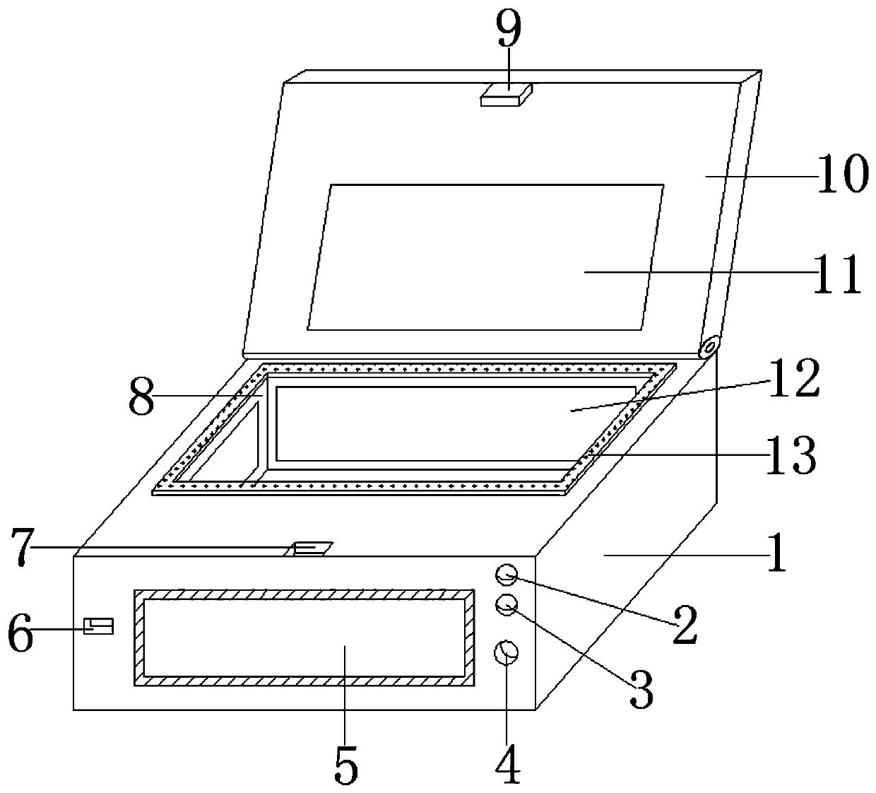
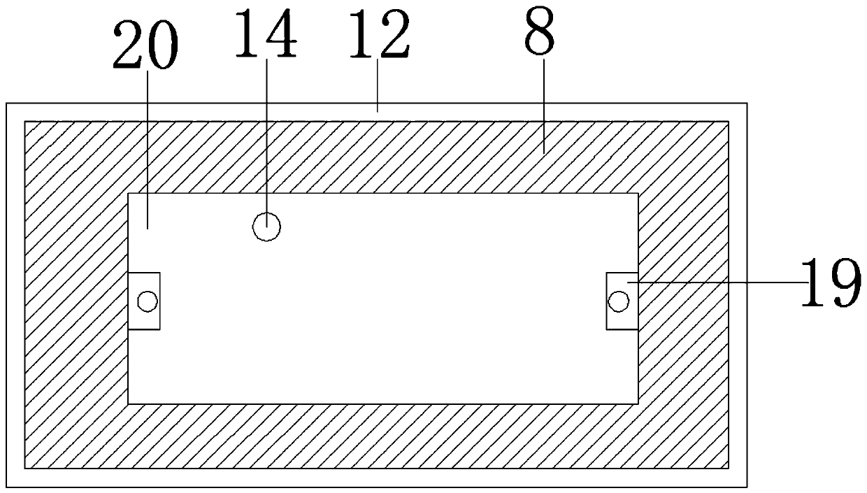
[0023] see figure 1 , 2 , a device for detecting high-temperature-resistant electric wires, including a detection box 1, a cover plate 10 is installed on the back of the top of the detection box 1 through bearings, a lock hook 9 is fixed in the middle of the front top of the cover plate 10 by screws, and a detection point 8 is arranged on the front of the cover plate 10 , a heat insulation board is arranged in front of the detection place 8, and the heat insulation board is fixed on the inner wall of the detection box 1 by screws. Plate 19, a column is arranged in the middle of the top of the fixed plate 19, the column and the fixed plate 19 are integrally formed, and the temperature sensor 14 is installed on the left side of the top rear of the detection plate 20 by embedding. The defect unevenness detector 11 is installed in the middle by embedding. The model of the defect unevenness detector 11 is: FDM-3028. The defect unevenness detector 11 corresponds to the position of ...
Embodiment 2
[0026] see figure 1 , 3 , a device for detecting high-temperature-resistant electric wires, including a detection box 1, a data interface 6 is embedded and installed on the left side of the front of the detection box 1, and a display 5 is arranged on the right side of the data interface 6, and the display 5 is embedded and fixed on the detection box 1 by bolts On the top, the display 5 is a touch screen display, and two buttons are fixed by screws on the upper right side of the display 5, which are respectively button a2 and button b3. It is fixed on the detection box 1 by screws. There is a controller 17 on the front left side of the detection box 1. The controller 17 is fixed in the detection box 1 by screws. The ammeter 16 is installed on the right side of the controller 17. The model of the ammeter 16 is: MNT03006 , there is a storage device 18 under the ammeter 16, the model of the storage device 18 is: JS28F640P33T85, the right side of the storage device 18 is provided ...
PUM
 Abstract
Description
Claims
Application Information
 - R&D Engineer
- R&D Manager
- IP Professional
- Industry Leading Data Capabilities
- Powerful AI technology
- Patent DNA Extraction
Browse by: Latest US Patents, China's latest patents, Technical Efficacy Thesaurus, Application Domain, Technology Topic, Popular Technical Reports.
© 2024 PatSnap. All rights reserved.Legal|Privacy policy|Modern Slavery Act Transparency Statement|Sitemap|About US| Contact US: help@patsnap.com