
Multi-wire pulley

A technology for pulleys and fixed pulleys, which is applied in the direction of belts/chains/gears, portable lifting devices, transmission parts, etc., which can solve the problem of not being on the center plane of the pulley, the damage of the cantilever deformation of the shackle pulley, increasing the use cost and carrying Burden and other issues, to achieve the effect of long service life

Active Publication Date: 2020-02-11
ZHEJIANG RUNVA MECHANICAL & ELECTRICAL
View PDF8 Cites 0 Cited by
  • Summary
  • Abstract
  • Description
  • Claims
  • Application Information

AI Technical Summary

Problems solved by technology

[0005] 1. The shackle-type pulley cantilever will be deformed after a long time of pulling, so that the surface-to-surface fit gap between the pulley cantilever and the pulley will become larger, which may cause the steel rope to be stuck between the pulley cantilever and the pulley. within the fitting gap;
[0006] 2. The pulley cantilever on the traditional shackle pulley is composed of two separate cantilevers. When traction in one direction is required, the two cantilevers are combined to form a complete pulley cantilever. When two traction ropes are required to pull from different directions , expand the two cantilevers, and one cantilever completes the traction in one direction, so that the cantilever is too thin, which may cause the deformation and damage of the cantilever of the shackle pulley, which will affect the traction;
[0007] 3. The pulley on the traditional shackle pulley can only go around one strand of steel wire rope. When the winch and the pulley are required to form a pulley block to achieve labor-saving purposes, a multi-wire shackle pulley is required. Generally, one or two wire pulleys are used. When the line pulley is used, its force is not on the center surface of the pulley, so it is generally necessary to carry two sets of pulleys, which increases the cost of use and the burden of carrying

Method used


Image

  • Multi-wire pulley
  • Multi-wire pulley
  • Multi-wire pulley

Examples


Embodiment Construction

[0036] The specific implementation manners of the present invention will be further described in detail below in conjunction with the accompanying drawings and embodiments. The following examples or drawings are used to illustrate the present invention, but not to limit the scope of the present invention.

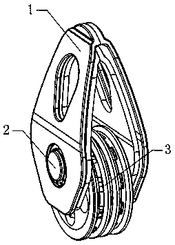
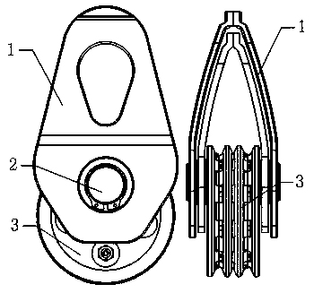
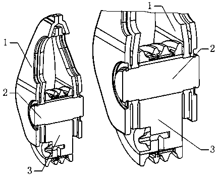
[0037] Such as figure 1 , 2 As shown, it includes a pulley mechanism 3 for the steel rope to go around, a fixed pulley mechanism 3 and a pulley cantilever 1 for installing a traction rope, a pin shaft 2 connecting the pulley mechanism 3 and the pulley cantilever 1, and is characterized in that: Figure 9 As shown, the pulley mechanism 3 is composed of an installation wheel 10, an installation runner 11 and two slip rings 20, as image 3 As shown, the installation wheel 10 is eccentrically installed on the pin shaft 2, the installation runner 11 is nested and installed on the outside of the installation wheel 10 through rotation and fit, two slip rings 20 are nested and in...


PUM


Abstract

The invention belongs to the technical field of pulleys, and particularly relates to a multi-wire pulley. The multi-wire pulley comprises a pulley mechanism for allowing a steel rope to bypass, a pulley cantilever which fixes the pulley mechanism and is provided with traction ropes, and a pin which is connected with the pulley mechanism and the pulley cantilever. According to the multi-wire pulley, under the same requirement of the pulley cantilever, the arm distance of the pulley cantilever in the designed shackle-type pulley is shorter relative to the arm distance of a pulley cantilever on atraditional shackle-type pulley; after the multi-wire pulley is used for a long time, the increasing degree of a cooperative gap of a surface and a surface between the pulley cantilever and the pulley mechanism is small, so that the probability that the gap clamps the steel rope is relatively small, and the service life is long; and the pulley cantilever is composed of two first cantilevers and two second cantilevers, when the two traction ropes are required to move in a traction mode from different directions, the two first cantilevers and the two second cantilevers are unfolded to the two sides to form two traction points of the pulley cantilever in different directions, the pulley cantilever of each directional traction point is of a double-sided structure, and the strength is higher.

Description

[0001] Technical field [0002] The invention belongs to the technical field of pulleys, in particular to a multi-wire pulley. Background technique [0003] At present, off-road vehicles often use winches, pulley shackles and other escape equipment in the off-road process. During use, winches and pulley shackles are used in combination. The use of winches can be divided into first-line, second-line and third-line methods. [0004] The shackle pulley is composed of a pulley for the steel rope to bypass and a pulley cantilever with a traction rope connected by a pin shaft. The two pulley cantilever can be rotated and opened relative to each other; the steel wire rope is wound on the pulley, even if there is no opening. Rings can be wrapped around pulleys; however, there are three problems with traditional shackle pulleys: [0005] 1. The shackle-type pulley cantilever will be deformed after a long time of pulling, so that the surface-to-surface fit gap between the pulley cantil...

Claims


Application Information

Patent Timeline
Patent Type & Authority Applications(China)
IPC IPC(8): B66D1/28
CPCB66D3/08B66D1/74F16H55/50F16H57/043
Inventor 俞芷琳戴林吉张小彬叶岭
Owner ZHEJIANG RUNVA MECHANICAL & ELECTRICAL
Learn More