Simple optical fiber cladding light stripping structure

A fiber cladding and simple structure technology, applied in the structure/shape of the active medium, lasers, laser components, etc., can solve the problem of limiting the power carrying capacity of cladding optical strippers, poor high temperature resistance of high-refractive-index glue, and glue Low ignition temperature and other issues, to achieve the effect of increasing the optical power that can be carried, good high temperature tolerance, and improving heat tolerance

Pending Publication Date: 2020-02-07
佛山市宝光新宇实业有限公司
View PDF0 Cites 2 Cited by
  • Summary
  • Abstract
  • Description
  • Claims
  • Application Information

AI Technical Summary

Problems solved by technology

Traditional cladding light strippers are coated with high-refractive-index glue on the cladding surface of the optical fiber, so that the cladding light is refracted or scattered out of the cladding. The glue has a low ignition temperature. If the heat dissipation is not good, there is a risk of burning , so it needs to be cooled by a high-strength water heat sink to work stably. When using it, it is necessary to fully consider the heat dissipation problem, and the high-refractive index glue itself has poor high temperature tolerance, which limits the power of the cladding optical stripper with this structure. Carrying capacity

Method used


Image

  • Simple optical fiber cladding light stripping structure
  • Simple optical fiber cladding light stripping structure
  • Simple optical fiber cladding light stripping structure

Examples


Embodiment Construction

[0025] The present invention will be described in detail below in conjunction with specific embodiments.

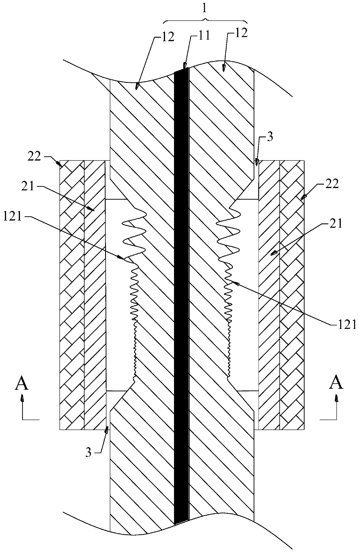
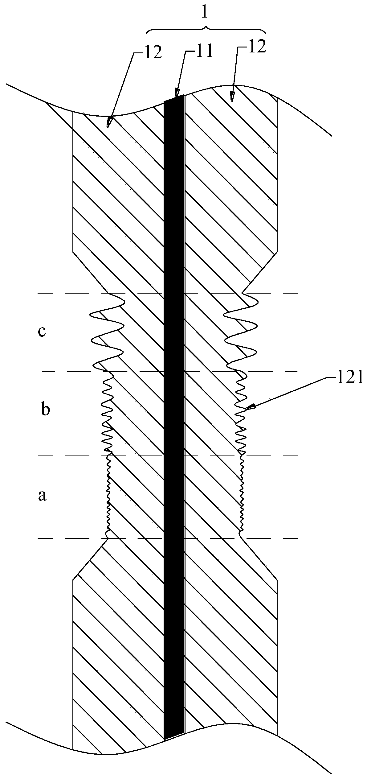
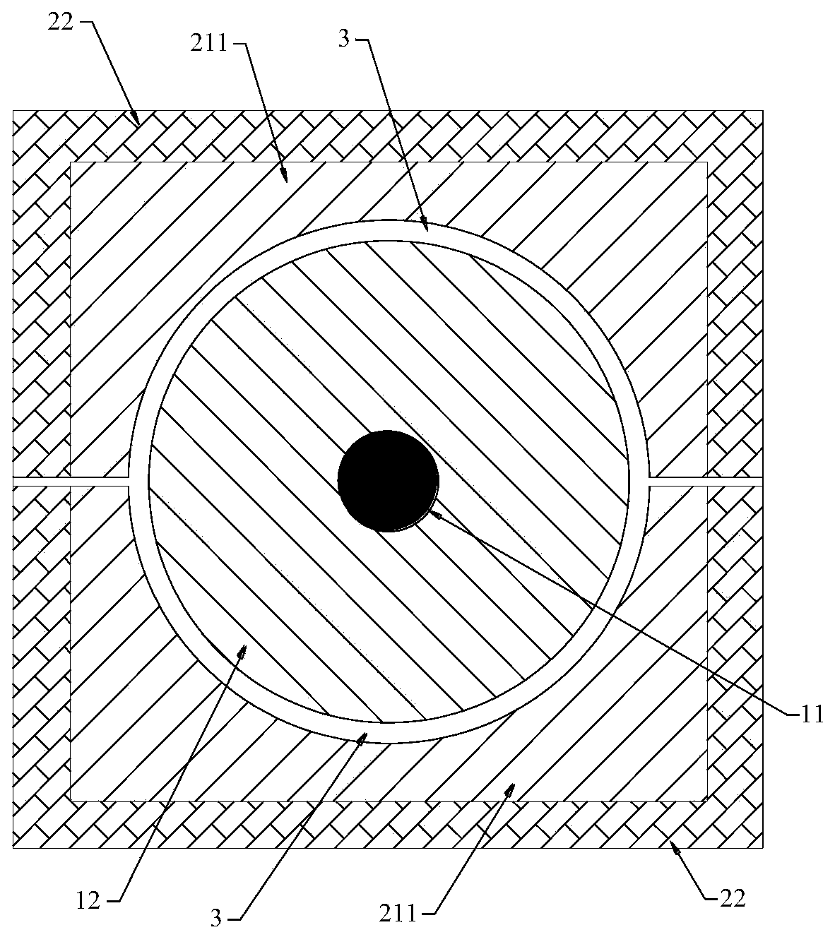
[0026] Such as figure 1 As shown, the optical fiber 1 includes a core and a cladding 12. The optical fiber cladding light stripping structure of this embodiment includes a rough scattering surface 121 and a light-transmitting heat dissipation sleeve 21. Preferably, the heat dissipation sleeve 21 is made of sapphire As a result, sapphire has good thermal conductivity and can dissipate heat quickly. The scattering surface 121 is obtained by destroying the outer surface of the cladding 12 . In this embodiment, the scattering surface 121 is preferably obtained by corroding the outer surface of the cladding 12 with hydrofluoric acid. The cooling sleeve 21 is provided with holes through the front and back (the direction from the front to the back defined herein, in figure 1 , figure 2 The middle is the direction from bottom to top), the optical fiber 1 runs through the tunn...


PUM

PropertyMeasurementUnit
refractive indexaaaaaaaaaa

Abstract

A simple optical fiber cladding light stripping structure relates to the technical field of optical fiber devices. The simple optical fiber cladding light stripping structure comprises a scattering surface which is formed on an outer surface of an optical fiber cladding by destroying the outer surface. The optical fiber cladding light stripping structure further comprises a light-transmitting heatdissipation sleeve which is provided with a hole channel running through the front and back of the sleeve. An optical fiber penetrates through the hole channel, so that the heat dissipation sleeve sleeves the outer side of the scattering surface. The heat dissipation sleeve is fixed to the optical fiber, and a gap is formed between the heat dissipation sleeve and the scattering surface. The heatdissipation sleeve comprises at least two splicing pieces. The heat dissipation sleeve is formed by splicing the at least two splicing pieces, so that the heat dissipation sleeve can sleeve the outerside of the scattering surface without cutting off the optical fiber. A rough scattering surface is formed, so that the total reflection condition of cladding light transmission is destroyed, claddinglight can be refracted or scattered out of the cladding, and cladding light stripping is realized. No medium (such as high-refractive-index glue) which is easy to thermally damage is used on the scattering surface (an area which is easy to heat), and the heat bearing capacity is greatly improved.

Description

technical field [0001] The invention relates to the technical field of optical fiber devices. Background technique [0002] In high-power all-fiber lasers, the cladding of the fiber inevitably contains residual pumping light, amplified spontaneous emission, and signal light leaked due to factors such as non-ideal fusion splicing and fiber bending, which will deteriorate the output laser beam quality, and even damage the semiconductor pumping source and other fiber optic devices in the laser system, which seriously affects the stability of the laser. Therefore, how to reliably and efficiently strip the cladding light from the cladding is one of the key issues in the development of high-power all-fiber lasers. [0003] The cladding light stripper is a passive device used to eliminate the cladding light in the optical fiber. Its basic working principle is to refract or scatter the cladding light out of the cladding by destroying the total reflection condition of the cladding l...

Claims


Application Information

Patent Timeline
Patent Type & Authority Applications(China)
IPC IPC(8): H01S3/067H01S3/04
CPCH01S3/0401H01S3/0407H01S3/06729
Inventor 湛欢王亦军李震汪树兵钟辉
Owner 佛山市宝光新宇实业有限公司
Why Eureka
Try Eureka