
Metal lamp housing provided with curled edge and edge curling device thereof

A technology of crimping device and lamp housing, which is applied in lighting devices, damage prevention measures of lighting devices, lighting and heating equipment, etc. Aesthetics and other issues, to achieve the effect of novel products, compact device structure, and ingenious design

Active Publication Date: 2020-02-07
NINGBO THREE PROOF LIGHTING TECH CO LTD
View PDF11 Cites 0 Cited by
  • Summary
  • Abstract
  • Description
  • Claims
  • Application Information

AI Technical Summary

Problems solved by technology

[0002] Figure 6-8 Shown is a rectangular metal lamp housing. The metal lamp housing is made of a thin metal plate through two processes of punching and stamping to obtain the lamp housing main body and the flange. After the lamp housing is formed, punching will leave behind the flange. The toughness, the toughness is easy to scratch the hands of the staff, and also affects the overall aesthetics of the metal lamp housing, so it is necessary to curl the metal lamp housing. The technology for the curling of the round cover has been relatively mature, and for The metal lamp housing requires the movement track of the coiler to be a rectangle. There is no corresponding curling device in the prior art, and there is no metal lamp housing with curling on the market.

Method used


Image

  • Metal lamp housing provided with curled edge and edge curling device thereof
  • Metal lamp housing provided with curled edge and edge curling device thereof
  • Metal lamp housing provided with curled edge and edge curling device thereof

Examples


Embodiment Construction

[0025] Such as Figure 6-8 As shown, the embodiment of the present invention provides a metal lamp housing with crimping on the one hand, including the lamp housing main body 16 and the crimping 161 located on the periphery of the lamp housing main body 16, and the crimping 161 is turned outward to form a hook-shaped crimping ;

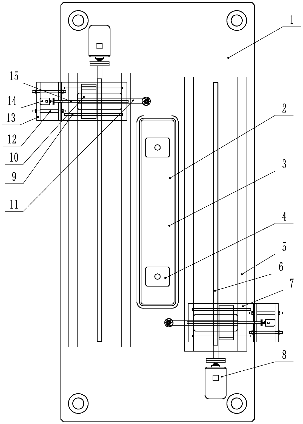
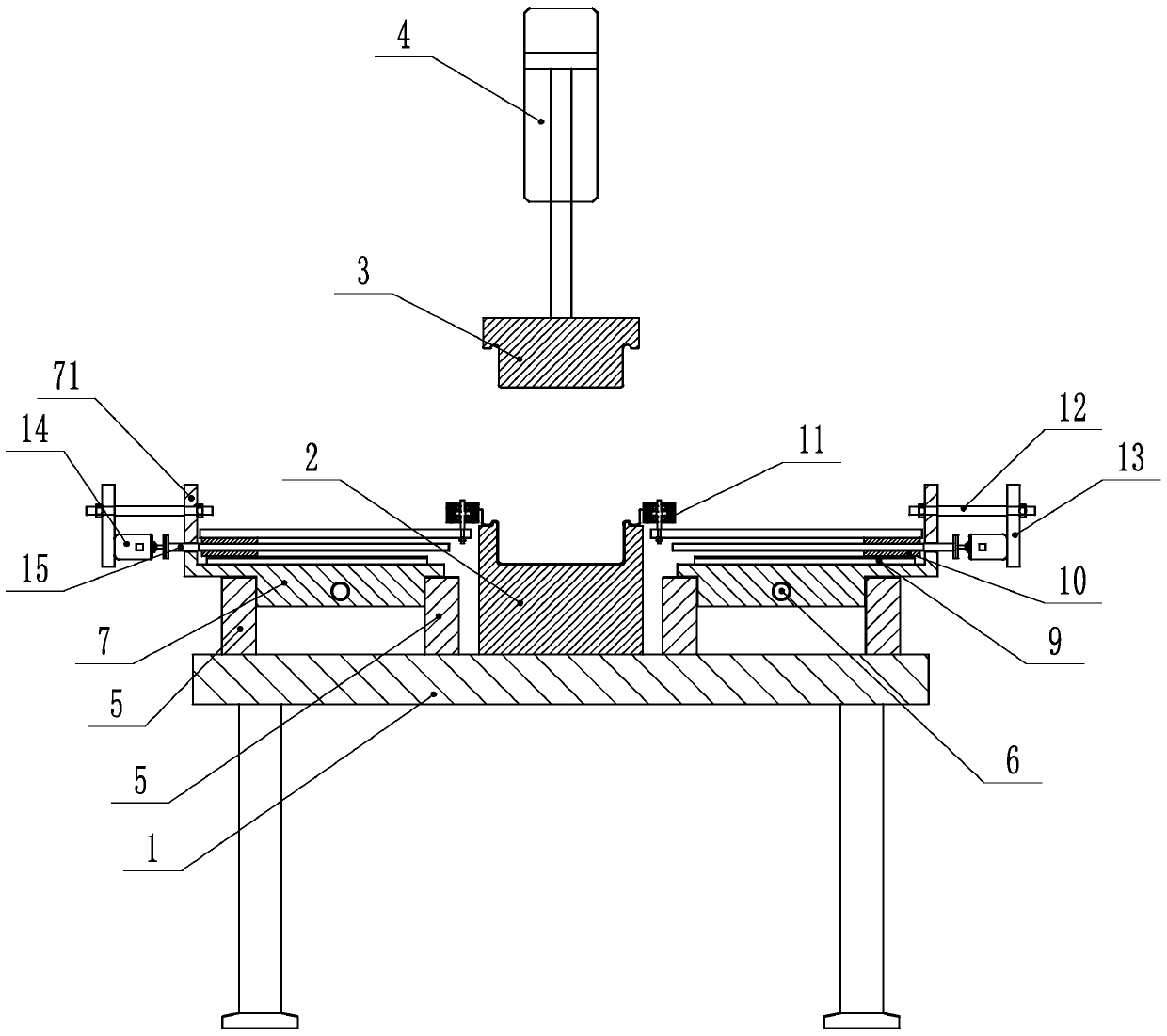
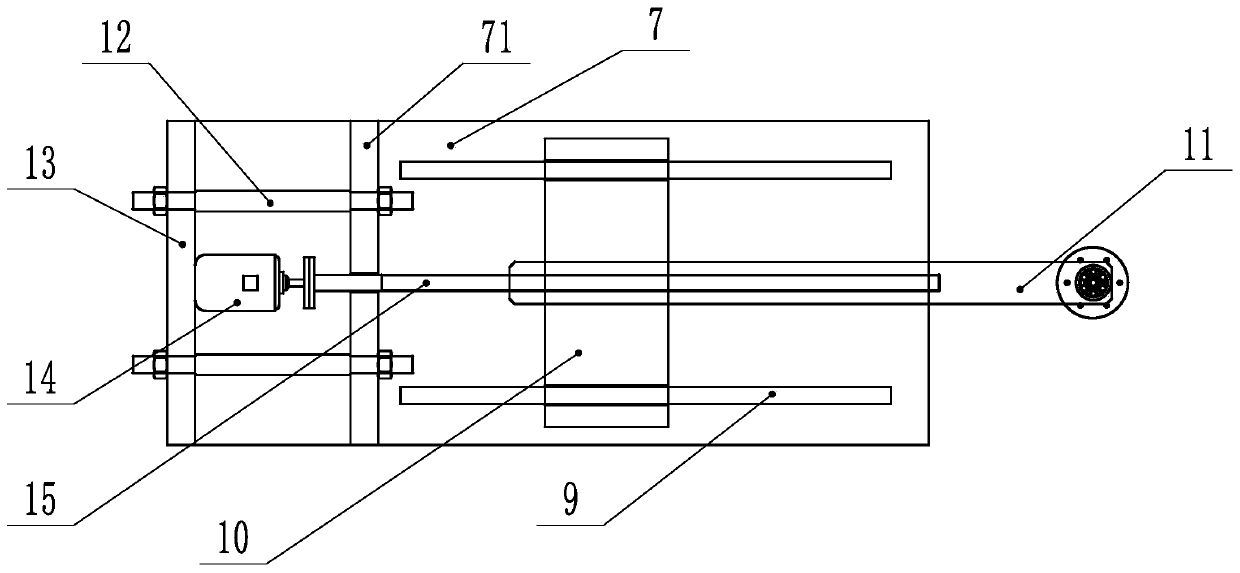
[0026] Such as Figure 1~4 As shown, another aspect of the embodiment of the present invention provides a crimping device for a metal lamp housing with crimping, including a workbench 1, and a middle part of the workbench 1 is fixed along the long side direction for placing the lamp housing main body 16. The lower positioning mold 2 is fixed on the top of the worktable 1, and the cylinder 4 is fixed on the shaft end of the cylinder 4. The upper positioning mold 3 matching the lamp housing main body 16 is fixed, and the workbench 1 is installed on both sides of the lower positioning mold 2 along the length direction. The first slideway 5, the first sl...


PUM


Abstract

The invention provides a metal lamp housing provided with a curled edge on one hand. The metal lamp housing comprises a lamp housing main body and a pressing edge on the periphery of the lamp housingmain body, wherein the pressing edge curls outwards to form a hooked curled edge. The invention provides an edge curling device of the metal lamp housing provided with the curled edge on the other hand. The edge curling device comprises a working table, wherein a lower positioning die is fixed in the middle of the working table; an upper positioning die is arranged above the lower positioning die;first slideways are mounted on the two sides of the working table in the length direction; a first sliding block is erected on each first slideway; a second slideway is mounted on each first slidingblock; a second sliding block is erected on each second slideway; an edge curling component is mounted on each second sliding block; and the edge curling device is controlled by a PLC in a unified manner. By means of the edge curling device of the metal lamp housing, the problem that edge curling in the prior art is difficult, so that the metal lamp housing provided with the curled edge is absenton the market is solved, and the edge curling component feeds under control of the PLC to realize edge curling of the metal lamp housing; and the edge curling device is skillful in design, and the processed product is absent on the market and is novel.

Description

technical field [0001] The invention relates to a metal lamp shell with crimping and a crimping device of the lamp shell. Background technique [0002] Figure 6-8 Shown is a rectangular metal lamp housing. The metal lamp housing is made of a thin metal plate through two processes of punching and stamping to obtain the lamp housing main body and the flange. After the lamp housing is formed, punching will leave behind the flange. The toughness, the toughness is easy to scratch the hands of the staff, and also affects the overall aesthetics of the metal lamp housing, so it is necessary to curl the metal lamp housing. The technology for the curling of the round cover has been relatively mature, and for The metal lamp housing requires that the motion track of the coiler be a rectangle. There is no corresponding curling device in the prior art, and there is no metal lamp housing with curling on the market. Contents of the invention [0003] In view of the deficiencies in the a...

Claims


Application Information

Patent Timeline
Patent Type & Authority Applications(China)
IPC IPC(8): F21V15/01B21D19/12
CPCF21V15/01B21D19/12Y02P40/57
Inventor 黄立
Owner NINGBO THREE PROOF LIGHTING TECH CO LTD
Learn More