Hydrodynamic transmission for large and medium-sized agricultural machines

A hydraulic transmission, large and medium-sized technology, applied in mechanical equipment, fluid transmission devices, belts/chains/gears, etc., can solve the problems of difficult processing, high production cost, and difficulty of bearing parts of clutch shafts, and achieves a reduction in The effect of oil leakage risk, low production cost and cost reduction

Inactive Publication Date: 2020-02-07
CHANGYI BAOLUDA MACHINERY MFG
View PDF0 Cites 0 Cited by
  • Summary
  • Abstract
  • Description
  • Claims
  • Application Information

AI Technical Summary

Problems solved by technology

[0003] 1. Unreasonable oil pipe layout
[0004] The gearbox in the prior art generally has six high-pressure oil pipes to provide working oil to the six clutches from the electronically controlled control valve, and the six high-pressure oil pipes are all external rubber hoses, the oil pipes are long, and the production cost is high. In addition, the loader The working environment is harsh, and rubber oil pipes are prone to aging and oil leakage when exposed to harsh environments for a long time, which shortens the service life of oil pipes and increases maintenance costs
[0005] 2. The installation position of the oil pump is unreasonable
The cleanliness of the oil used by the oil pump is high. When the built-in oil pump fails, the gearbox must be disassembled for maintenance and replacement, so maintenance is inconvenient, which increases the difficulty of maintenance and prolongs the maintenance time
[0007] 3. The bearing parts of the clutch shaft are difficult to process
[0008] The gearbox clutch structure adopts a fixed clutch shaft, and the bearing only retains cylindrical rollers. The outer diameter of the clutch shaft and the inner diameter of the gear are bearing raceways, and the outer diameter of the clutch shaft and the inner diameter of the gear are processed according to the bearing standard. high production cost

Method used


Image

  • Hydrodynamic transmission for large and medium-sized agricultural machines
  • Hydrodynamic transmission for large and medium-sized agricultural machines
  • Hydrodynamic transmission for large and medium-sized agricultural machines

Examples


Embodiment Construction

[0028] Below in conjunction with accompanying drawing and embodiment, further elaborate the present invention. In the following detailed description, certain exemplary embodiments of the invention are described by way of illustration only. Needless to say, those skilled in the art would realize that the described embodiments can be modified in various different ways, all without departing from the spirit and scope of the present invention. Accordingly, the drawings and description are illustrative in nature and not intended to limit the scope of the claims.

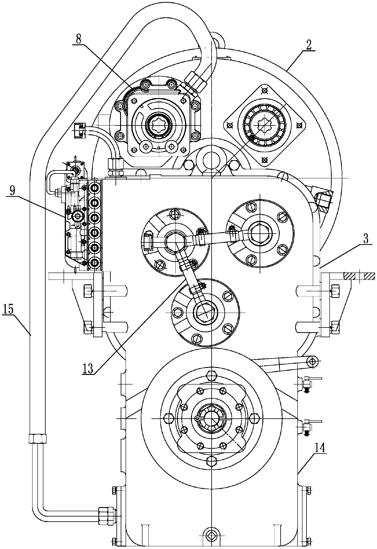
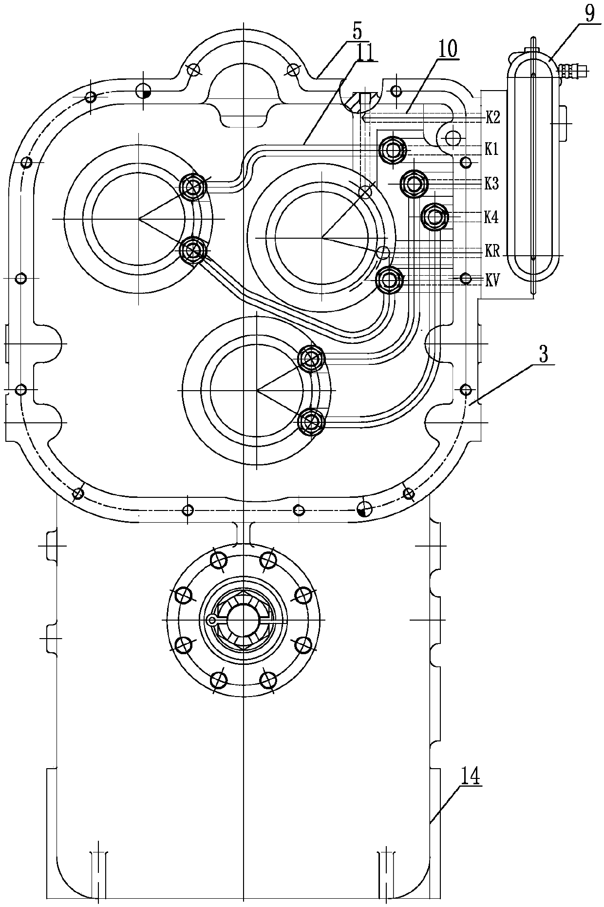
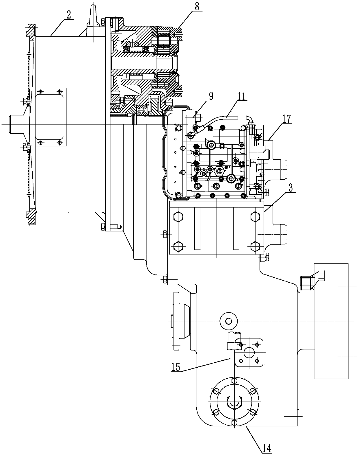
[0029] Such as figure 1 , figure 2 , image 3 , Figure 4 with Figure 5 As shown, the hydraulic transmission for large and medium-sized agricultural machinery includes an input shaft 1 connected to the engine transmission, and a torque converter 2 and a gearbox 3 are sequentially rotated on the input shaft 1. The specific structure of the torque converter 2 is As is well known to those of ordinary skill in the art...


PUM


Abstract

The invention discloses a hydrodynamic transmission for large and medium-sized agricultural machines. The hydrodynamic transmission comprises a torque converter and a gearbox. The gearbox comprises abox housing, at least two sets of clutch mechanisms are arranged in the box housing in a parallel and rotary manner, an external oil pump is fixedly installed on the outer side of the gearbox and connected with an electric control operating valve, an internal oil channel connecting the electric control operating valve with one of the clutch mechanisms is arranged in the box housing, and internal oil pipes connecting the other clutch mechanisms with the electric control operating valve are also packaged in the box housing. The external oil pump is installed outside the box housing, when the oilpump fails, the oil pump is directly repaired without the need of disassembling or assembling the whole structure, and maintenance is convenient. Only four short oil pipes are needed for the internaloil pipes, the other two internal oil channels are directly connected with the corresponding clutch mechanisms by drilling holes in the side wall of the box housing, the internal oil pipes are not prone to damage and are long in service life, and the oil leakage risk is reduced. Each clutch mechanism is provided with a rotary clutch shaft, the manufacturing cost is low, and the universality is high.

Description

technical field [0001] The invention relates to the technical field of power transmission equipment, in particular to a hydraulic transmission for large and medium-sized agricultural machinery. Background technique [0002] At present, the multi-speed hydraulic transmission used on large and medium-sized agricultural machinery consists of a hydraulic torque converter and a multi-speed power shift gearbox. However, due to its unreasonable structural composition and configuration, it mainly includes the following aspects: [0003] 1. Unreasonable oil pipe layout [0004] The gearbox in the prior art generally has six high-pressure oil pipes to provide working oil to the six clutches from the electronically controlled control valve, and the six high-pressure oil pipes are all external rubber hoses, the oil pipes are long, and the production cost is high. In addition, the loader The working environment is relatively harsh, and rubber oil pipes are prone to aging and oil leakage...

Claims


Application Information

Patent Timeline
Patent Type & Authority Applications(China)
IPC IPC(8): F16H41/04F16H41/24
CPCF16H41/04F16H41/24
Inventor 李金鹏
Owner CHANGYI BAOLUDA MACHINERY MFG
Why Eureka
Try Eureka