Camera imaging error calibration method and correction method

An imaging error and calibration method technology, applied in the field of vision correction, can solve the problems of conflict between calculation accuracy and model accuracy, unstable solution, and camera installation error without considering lens tangential distortion, so as to simplify the calibration process and reduce time. Effects with Complexity

Active Publication Date: 2020-02-04
深圳为工智能科技有限公司
View PDF6 Cites 3 Cited by
  • Summary
  • Abstract
  • Description
  • Claims
  • Application Information

AI Technical Summary

Problems solved by technology

The disadvantages of this method are: the solution is unstable, the calculation accuracy and the model accuracy often conflict, and the perspective deformation caused by the camera installation error cannot be calibrated
The disadvantage of this method is: because the parameters obtained are the least squares solution, the accuracy is limited
At the same time, the tangential distortion of the lens and the installation error of the camera are not considered, and the correction effect on the distortion is not good, and the perspective distortion cannot be corrected.
[0010] It can be seen that there is currently no better calibration and correction method that can correct distortion and perspective distortion at the same time with high precision.

Method used


Image

  • Camera imaging error calibration method and correction method
  • Camera imaging error calibration method and correction method
  • Camera imaging error calibration method and correction method

Examples


Embodiment Construction

[0049] The present invention will be described in detail below in conjunction with the accompanying drawings and specific embodiments.

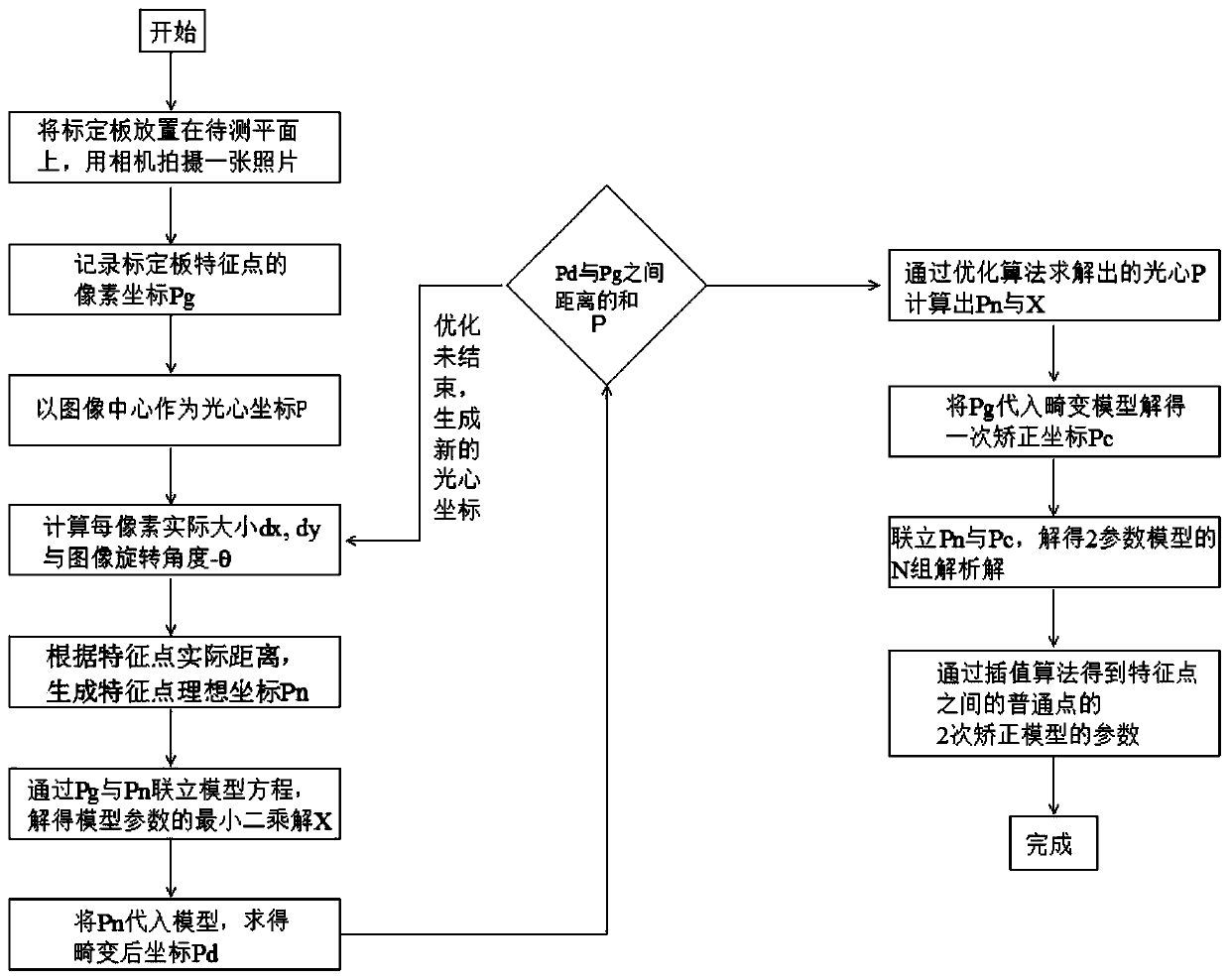
[0050] see figure 1 , the present invention provides a camera imaging error calibration method, comprising the following steps:

[0051] Step 1: Place the calibration plate on the plane to be tested, shoot the calibration plate with a camera, and send the captured original image to the imaging processing device. Among them, the calibration plate is a precision calibration plate, which is placed on a substrate with high strength and small deformation to write regular patterns, and the precision of the pattern writing determines the upper limit of the accuracy that can be achieved by the method disclosed in the present invention. Generally adopt the traditional calibration method, it is necessary to place the calibration plate in front of the camera to take multiple images from different distances, different positions and different angles, gen...


PUM


Abstract

The invention discloses a camera imaging error calibration and correction method. A secondary calibration model is introduced to solve the problem that the correction precision is low due to calibration of a least square method commonly used at present, and camera installation errors cannot be corrected. According to the method, distortion and perspective deformation can be corrected at the same time in a high-precision mode, correction coordinates of characteristic points of the calibration plate completely coincide with ideal coordinates, correction parameters of the characteristic points are introduced into non-characteristic points through an interpolation algorithm, and high-precision correction of the whole image is achieved. Moreover, the traditional calibration method needs to process the images of a plurality of calibration plates, and the method only needs to process the image of one calibration plate, thereby simplifying the calibration process, and greatly reducing the timeand complexity of the calibration work.

Description

technical field [0001] The invention relates to the field of vision correction, in particular to a camera imaging error calibration and correction method. Background technique [0002] In the field of computer vision, an important application is to accurately image the shape on a certain plane in space so that it can be precisely measured. The manufacturing accuracy of the camera lens and the deviation of the assembly process will cause distortion, and the non-parallel imaging plane of the camera and the object plane will cause perspective distortion, both of which will lead to distortion of the imaging result. In order to correct the distortion, it is necessary to calibrate the error of the imaging system. There are three commonly used calibration methods and corresponding defects as follows: [0003] 1. Traditional camera calibration [0004] The simplest camera calibration is linear calibration, which does not consider the distortion of the camera but only considers th...

Claims


Application Information

Patent Timeline
Patent Type & Authority Applications(China)
IPC IPC(8): G06T7/80G06T3/00
CPCG06T7/80G06T3/04
Inventor 朱韬
Owner 深圳为工智能科技有限公司
Why Eureka
Try Eureka