
Color phase controller of projection display adopting three-D optical modulator

A technology of display system and color turntable, which is applied in the field of projection display system, can solve the problem of expensive high-torque motors, and achieve the effect of reducing human interference

Inactive Publication Date: 2003-04-30
TEXAS INSTR INC
View PDF6 Cites 0 Cited by
  • Summary
  • Abstract
  • Description
  • Claims
  • Application Information

AI Technical Summary

Problems solved by technology

However, such high torque motors are very expensive

Method used


Image

  • Color phase controller of projection display adopting three-D optical modulator
  • Color phase controller of projection display adopting three-D optical modulator
  • Color phase controller of projection display adopting three-D optical modulator

Examples


Embodiment Construction

[0023] See U.S. Patent No. 07 / 678,761 entitled "Structure and Timing Control of a DMD for a Pulse Width Modulated Display System" which describes a DMD-based projection display system without the features of the present invention . The patent also describes a method of formatting video data for use with the system, and a method of modulating the bit planes to provide a gray scale image. See US Patent No. 07 / 809,816, entitled "Color Field Sequential Projection with Enhanced White Light," which describes the general use of a DMD-based projection system with a color wheel to produce sequential color images.

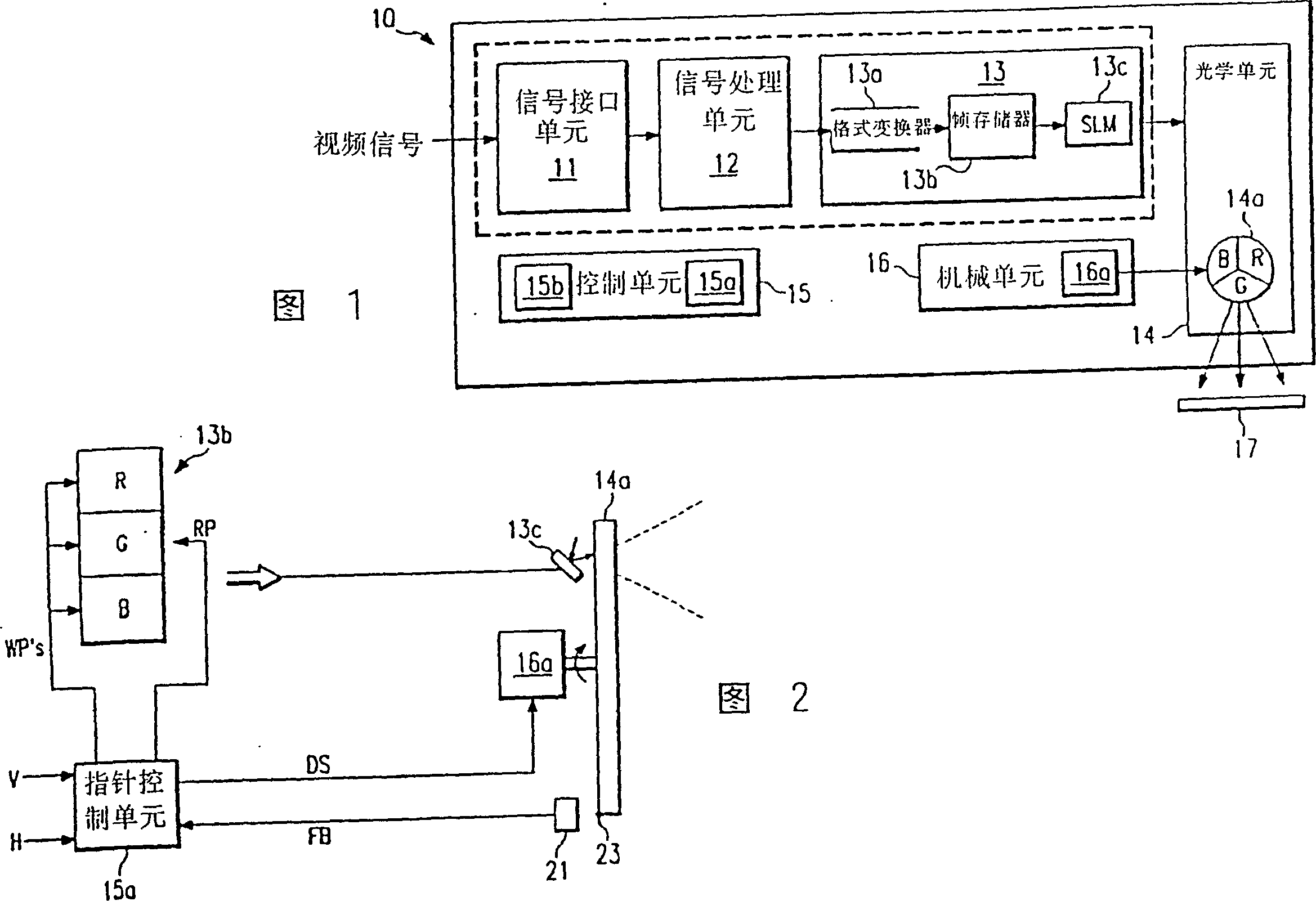
[0024] Figure 1 is a block diagram within an SLM-based projection display system that can generate color images from pixel sample data of a video signal. The video signal can be any signal whose pixel data can be sampled. For example: this video signal can be a TV broadcast signal, which can be sampled and converted into RBG data. This video signal may also be an RBG sign...


PUM


Abstract

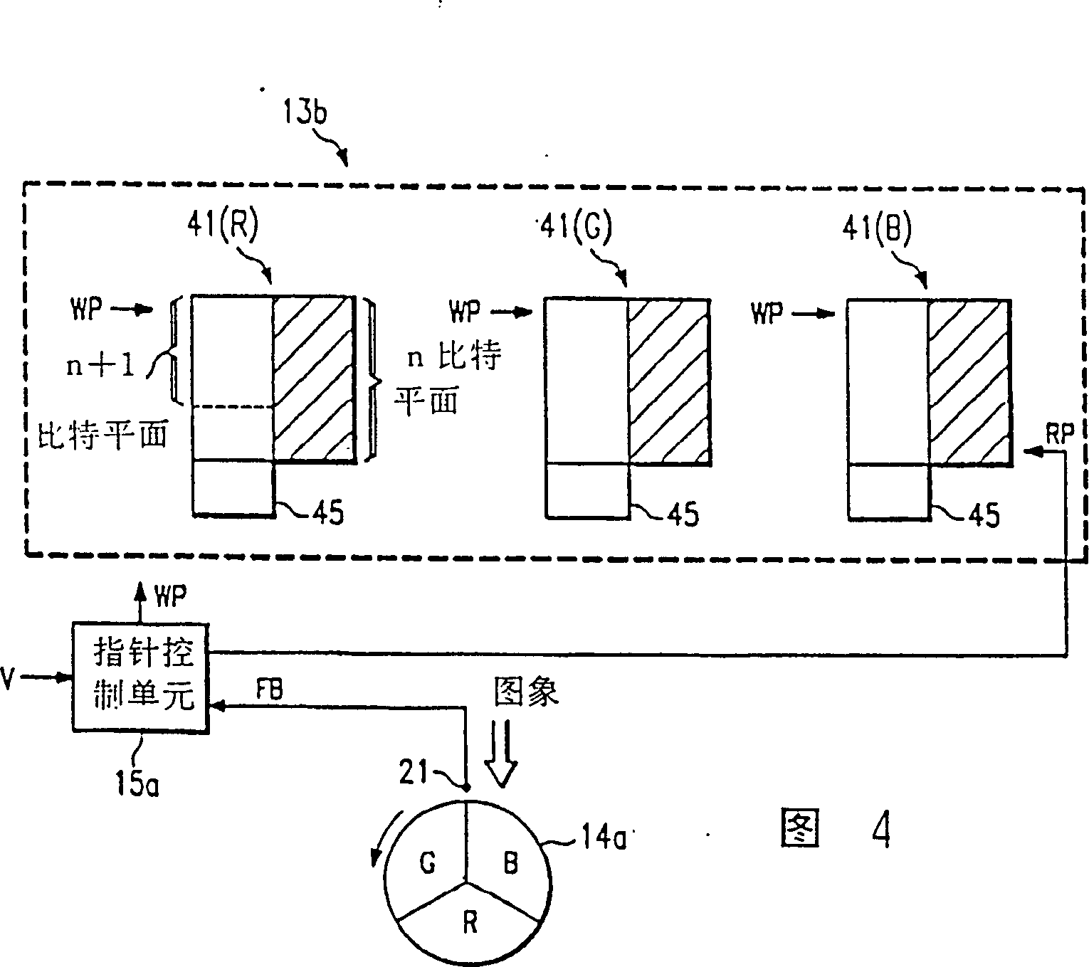
A SLM-based projection display system (10) samples and processes video data for delivery to a spatial light modulator (SLM) (13c), and uses a color wheel (14a) to color the SLM-generated images. A frame memory (13b) provides data to the SLM (13c) and is managed so that, if the phase of the incoming video signal changes, a desired phase relationship between the color wheel position and the data available to the SLM (13c) can be maintained. Also, a motor control unit (15a) uses a horizontal sync signal to generate a drive signal for the color wheel motor (16a), which limits the transient time during phase-changing events, and which provides a means for adjusting the phase of the drive signal.

Description

[0001] This application is a divisional application of the patent application "Color phase control system for projection display using three-dimensional optical modulator" filed on July 19, 1994 with application number 94116150.1. technical field [0002] The invention relates to an image display system, more specifically to a projection display system using a three-dimensional optical modulator, a white light source and a color turntable. Background technique [0003] Three-dimensional optical modulators (SLMs) are increasingly used in projection display applications. A DMD is a type of SLM with an array of micromechanical mirror elements, each of which is addressed by electronic data. Each mirror element moves according to the state of its address signal to reflect or not reflect light onto the image plane. [0004] In SLM-based display applications, the incoming video signal must be converted into a binary data form usable by the SLM. When an analog signal is converted ...

Claims


Application Information

Patent Timeline
Patent Type & Authority Patents(China)
IPC IPC(8): H04N9/31
CPCH04N9/3197G09G2310/0235H04N9/3179H04N9/3114H04N9/31
Inventor 杰弗里B·桑普塞尔理查德C·迈耶罗伯特J·戈夫斯蒂芬W·马歇尔唐纳德B·多尔蒂
Owner TEXAS INSTR INC
Learn More