
Particulate matter concentration prediction method and device, storage medium and electronic equipment

A particle concentration and particle technology, applied in the direction of measuring devices, forecasting, particle suspension analysis, etc., can solve problems such as uneven spatial distribution, no monitoring points, and inability to meet the needs of air pollution prevention and control

Active Publication Date: 2020-01-31
BEIJING UNIVERSITY OF CIVIL ENGINEERING AND ARCHITECTURE
View PDF7 Cites 5 Cited by
  • Summary
  • Abstract
  • Description
  • Claims
  • Application Information

AI Technical Summary

Problems solved by technology

[0003] At present, most of the accurate acquisition of particulate matter concentration in the air depends on ground air quality monitoring stations. However, the spatial distribution of ground air quality monitoring stations in my country's current national urban ambient air quality monitoring network is extremely uneven, mainly in urban areas or suburban areas, and slightly remote. of towns and villages do not have surveillance sites
As a result, there are still many "blind spots" in air quality evaluation, air pollution prevention and control, and precise haze control.
Therefore, the current method of obtaining the concentration of particulate matter in the air cannot accurately obtain the concentration of particulate matter in each location, and cannot meet the current needs of air pollution prevention and control

Method used


Image

  • Particulate matter concentration prediction method and device, storage medium and electronic equipment
  • Particulate matter concentration prediction method and device, storage medium and electronic equipment
  • Particulate matter concentration prediction method and device, storage medium and electronic equipment

Examples


Embodiment Construction

[0056] Specific embodiments of the present disclosure will be described in detail below in conjunction with the accompanying drawings. It should be understood that the specific embodiments described here are only used to illustrate and explain the present disclosure, and are not intended to limit the present disclosure.

[0057]Before introducing the implementation of the present disclosure in detail, the application scenarios of the present disclosure will be introduced first. The present disclosure can be applied to determine the particle concentration in an area where no near-surface air monitoring stations are set, and can also be used to obtain continuous data of the near-surface particle concentration. Spatial distribution status, wherein the particulate matter concentration may be PM2.5 concentration, PM10 concentration, or other respirable particulate matter concentration. Taking the concentration of PM2.5 as an example, the excessive concentration of PM2.5 is the dire...


PUM


Abstract

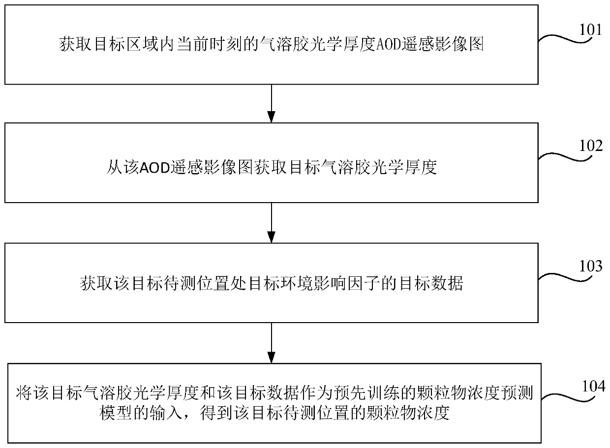
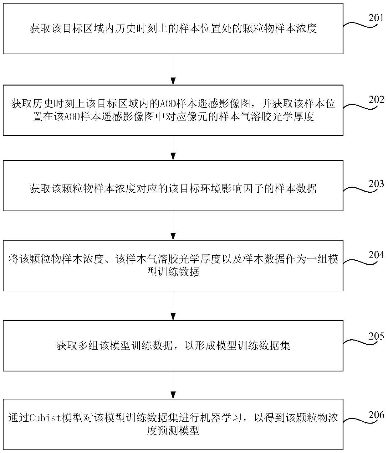
The invention relates to a particulate matter concentration prediction method and device, a storage medium and electronic equipment. The method comprises the steps of acquiring an aerosol optical thickness AOD remote sensing image map at the current moment in a target area; obtaining a target aerosol optical thickness from the AOD remote sensing image map, the target aerosol optical thickness being an aerosol optical thickness of a corresponding pixel of a target to-be-measured position in a target area in the AOD remote sensing image map; obtaining target data of a target environment influence factor at a target to-be-measured position; and taking the target aerosol optical thickness and the target data as the input of a pre-trained particulate matter concentration prediction model to obtain the particulate matter concentration at the target to-be-measured position. Therefore, the continuous spatial distribution of the near-surface particulate matter concentration can be accurately estimated by simultaneously fusing the ground air quality monitoring data, the satellite remote sensing data and the target environment influence factor data, so that a reliable data basis can be provided for comprehensively treating environmental problems.

Description

technical field [0001] The present disclosure relates to the field of air quality monitoring, and in particular, to a method, device, storage medium and electronic equipment for predicting particle concentration. Background technique [0002] The air pollution problem caused by particulate matter represented by PM2.5 has become the most urgent and prominent environmental problem in my country at present, and the severity of its psychological and physical health hazards to the public has aroused widespread concern in the society. [0003] At present, most of the accurate acquisition of particulate matter concentration in the air depends on ground air quality monitoring stations. However, the spatial distribution of ground air quality monitoring stations in my country's current national urban ambient air quality monitoring network is extremely uneven, mainly in urban areas or suburban areas, and slightly remote. There are no monitoring points in towns and villages. As a result...

Claims


Application Information

Patent Timeline
IPC IPC(8): G06Q10/04G06N20/00G06K9/62G01N15/06
CPCG06Q10/04G06N20/00G01N15/06G06F18/214
Inventor 周磊王娅妮王思宇杜明义靖常峰
Owner BEIJING UNIVERSITY OF CIVIL ENGINEERING AND ARCHITECTURE
Learn More