
Air OTA performance test system for out-of-band useless transmission indexes of wireless equipment

A wireless device and unwanted emission technology, which is applied in the direction of transmitter monitoring, etc., can solve the problems of hindering the application of the wireless device under test, the wireless device under test cannot pass the limit value requirements, and cannot truly reflect the level of unwanted emission of the wireless device under test. , to achieve the effect of low cost, good out-of-band unwanted emission index test results, and small footprint

Pending Publication Date: 2020-01-24
THE STATE RADIO MONITORING CENT TESTING CENT
View PDF0 Cites 6 Cited by
  • Summary
  • Abstract
  • Description
  • Claims
  • Application Information

AI Technical Summary

Problems solved by technology

[0003] In the prior art, the out-of-band unwanted emission indicators measured by ordinary methods usually cannot truly reflect the actual out-of-band unwanted emission level of the wireless device under test
For example, suppose the standard requires that the out-of-band unwanted emission index of the wireless device under test cannot be greater than -40dBm / MHz. Out-of-band unwanted emission index results may be -10dBm / MHz, -38dBm / MHz, -47dBm / MHz, etc., which cannot reflect the real level of the tested wireless device, and even cause the tested wireless device to fail to pass the standard out-of-band unwanted emission Specification limit requirements, hindering the application of the wireless device under test

Method used


Image

  • Air OTA performance test system for out-of-band useless transmission indexes of wireless equipment
  • Air OTA performance test system for out-of-band useless transmission indexes of wireless equipment

Examples


Embodiment Construction

[0042] Hereinafter, exemplary embodiments of the present disclosure will be described in more detail with reference to the accompanying drawings. Although exemplary embodiments of the present disclosure are shown in the drawings, it should be understood that the present disclosure can be implemented in various forms and should not be limited by the embodiments set forth herein. On the contrary, these embodiments are provided to enable a more thorough understanding of the present disclosure and to fully convey the scope of the present disclosure to those skilled in the art.

[0043] Nowadays, relevant international and domestic standards have put forward more stringent pass limit requirements for the out-of-band unwanted emission OTA test indicators of wireless transmitting devices. Taking 5G base stations as an example, the requirements for out-of-band unwanted emission indicators are more stringent than in the past. It is no longer like in the past. The limit of out-of-band unwa...


PUM


Abstract

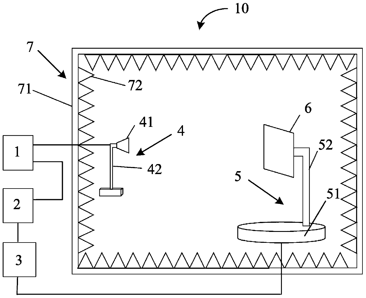
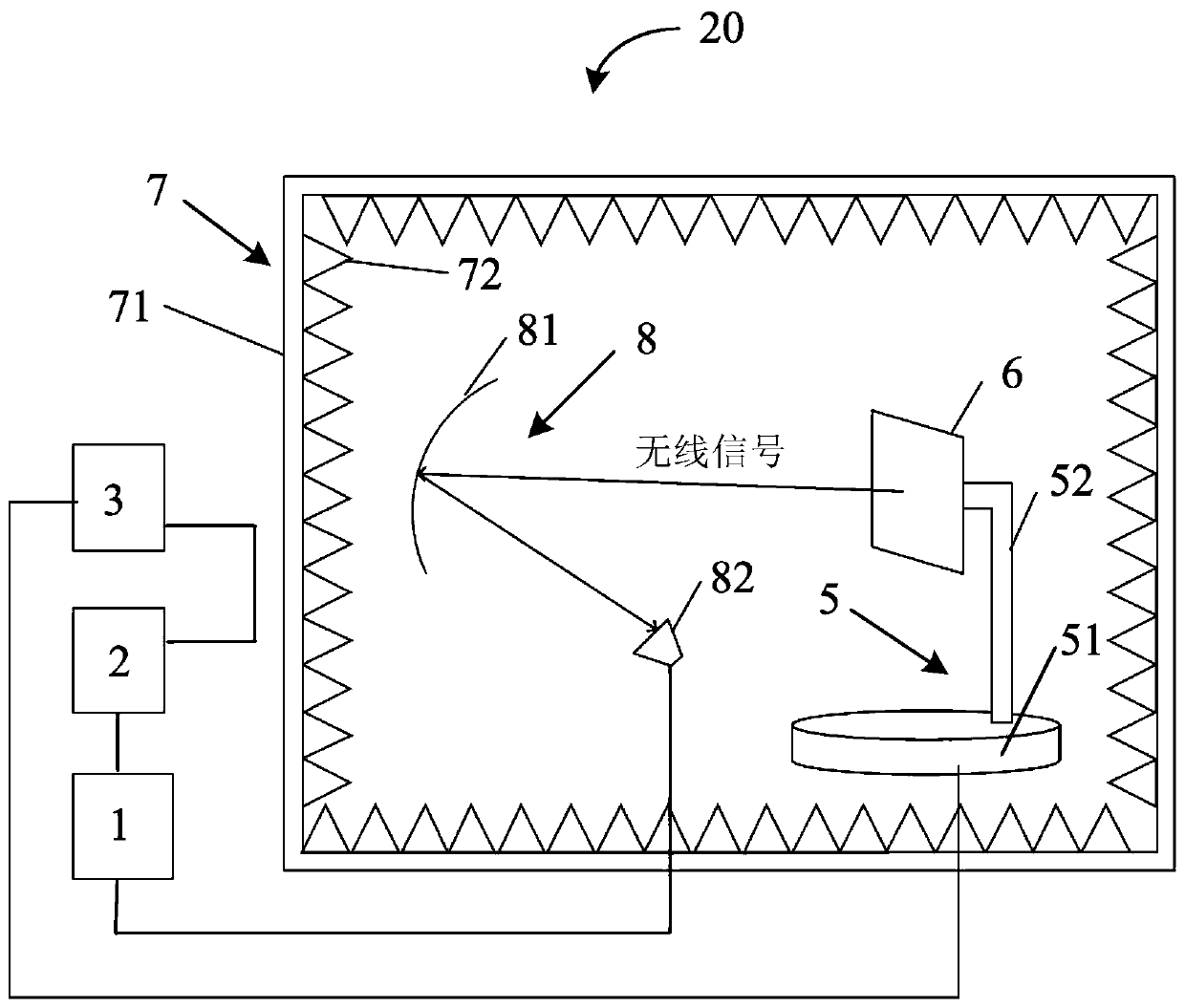
The invention provides an air OTA performance test system for out-of-band useless emission indexes of a wireless device. The system comprises a darkroom, a rotary table, a detected wireless device, asignal detection assembly, a spectrum analyzer and a control device, and the path loss of the darkroom is lower than the difference value between the required value of the out-of-band useless emissionindex of the detected wireless device and the bottom noise value of the spectrum analyzer. According to the invention, the darkroom with a specific path loss value is used as a test site; a single signal detection assembly is used as a probe to be matched with a rotary table capable of rotating horizontally and vertically to carry out near-field test on out-of-band useless emission indexes of tested wireless equipment; according to the invention, the overall offset compensation value of the field path loss and the cable loss on the spectrum analyzer can be effectively ensured to be small enough, so that the bottom noise of the whole test system can be effectively controlled, a stable and good out-of-band useless emission index test result can be obtained, and the index requirements of tested wireless equipment can be met. The test system is small in occupied area and low in cost.

Description

Technical field [0001] The invention relates to the technical field of wireless equipment testing, in particular to an over-the-air OTA performance test system for out-of-band useless emission indicators of wireless equipment. Background technique [0002] At present, although some recommendations have been given in the relevant international and domestic standards on the out-of-band unwanted emission OTA (Over the Air) test method of wireless devices (such as 5G base stations), there is no detailed test yet. Description of the method. Due to the increasing shortage of frequency resources, in order to avoid mutual interference between different systems, the National Radio Administration has put forward very strict out-of-band unwanted emission OTA test indicators for wireless transmission equipment (especially 5G base stations below 6GHz), but it has not targeted This rigorous indicator gives clear recommendations for methods that facilitate the passing of the test. [0003] In t...

Claims


Application Information

Patent Timeline
IPC IPC(8): H04B17/17
CPCH04B17/17
Inventor 宫剑张明远付靖
Owner THE STATE RADIO MONITORING CENT TESTING CENT
Learn More