
Camera support

A camera and host technology, which is applied in the field of camera equipment and photography, can solve problems such as blurred and distorted pictures, and achieve the effects of easy maintenance and replacement, improved picture clarity, and reduced shooting brightness

Inactive Publication Date: 2020-01-24
BAOSTEEL ENG & TECH GRP
View PDF5 Cites 0 Cited by
  • Summary
  • Abstract
  • Description
  • Claims
  • Application Information

AI Technical Summary

Problems solved by technology

[0003] The invention proposes a camera bracket, which is used to solve the problem in the prior art that the camera directly shoots the observation source with too high brightness to obtain a blurred and distorted picture

Method used


Image

  • Camera support
  • Camera support
  • Camera support

Examples


Embodiment 1

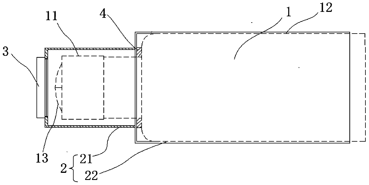
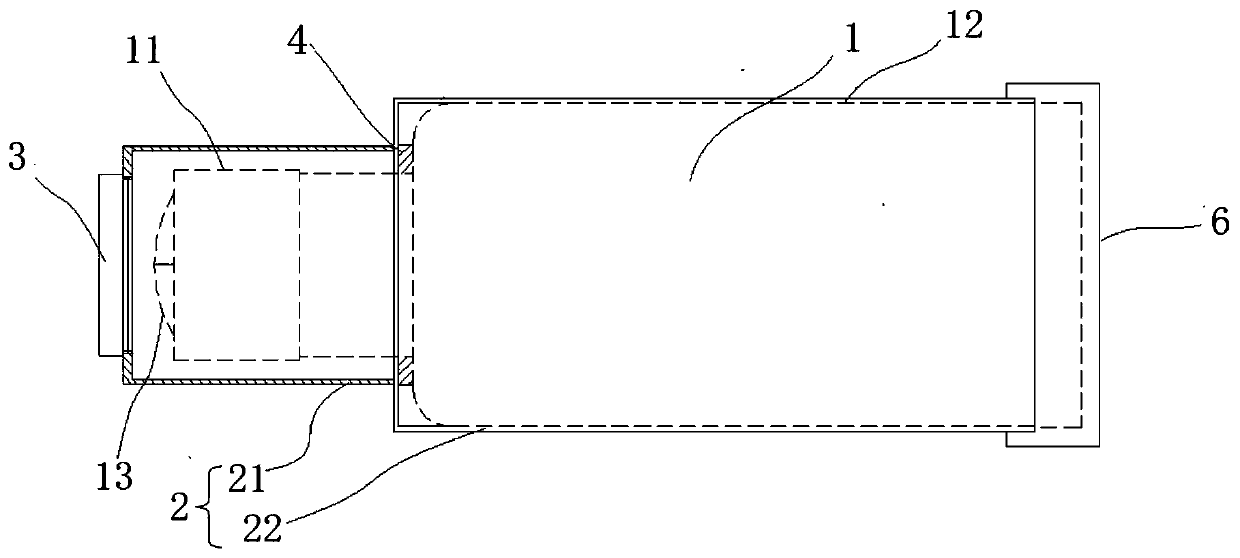
[0024] like figure 1 As shown, it is a sectional view of the installation of the camera bracket and the camera according to Embodiment 1 of the present invention. The camera bracket includes an outer shield 2 and a filter 3, the outer shield 2 has an inner cavity, the shape of the inner cavity matches the shape of the camera 1, so that the camera 1 is installed on the outer shield 2; the end of the outer shield 2 close to the camera lens 11 has a through hole matching the filter 3, and the filter 3 is detachably mounted on the through hole.

[0025] In this implementation, the outer shield 2 includes a lens outer shield 21 and a host outer shield 22, which are connected between the lens outer shield 21 and the host outer shield 22; 21 has a first inner cavity, and the first inner cavity is used to accommodate the camera lens 11, and the through hole is arranged on the lens outer shield 21; the host outer shield 22 has a second inner cavity , the second inner cavity is used f...

Embodiment 2

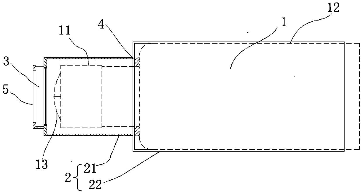
[0033] The difference from Embodiment 1 is that: the lens outer shield 21 of this embodiment includes a filter fixing ring 211 and a lens outer shield main body 212 . like Figure 4 and 5 As shown, the filter fixing ring 211 is detachably connected to the lens outer shield main body 212 , and the through hole is provided on the filter fixing ring 211 . like Figure 4 and 5 In the shown camera bracket, the filter 3 and the filter fixing ring 211 are respectively connected by threads and slots. Of course, other detachable connection methods can also be used between the filter 3 and the filter fixing ring 211 .

[0034] It should be noted that the camera bracket of the present invention is often used in high-temperature environments such as steelmaking, refining, continuous casting, and hot rolling. The position of the filter fixing ring 211 is closest to the high-temperature environment, and is easily damaged by the high-temperature environment. Therefore, the detachable con...


PUM


Abstract

The invention provides a camera support, which comprises an outer shield and a filter. The outer shield is provided with an inner cavity, and the shape of the inner cavity is matched with that of a camera, so that the camera can be arranged in the inner cavity of the outer shield. A through hole matched with the filter is formed in the end, close to the camera lens, of the outer shield, and the filter is detachably installed on the through hole. The camera carries out shooting through the filter on the camera support, so that the shooting brightness of a high-brightness observation source canbe reduced, and the picture definition of the camera can be improved. Meanwhile, a filter fixing ring is detachably connected with the outer shield, so that the filter is convenient to maintain and replace.

Description

technical field [0001] The invention relates to photography and camera equipment, in particular to a camera bracket. Background technique [0002] At present, when observing furnace water, slag, strip steel and other technological processes in steelmaking, refining, continuous casting, hot rolling and other areas, cameras are often used for observation. However, since these areas are highlighted areas of open flames, the brightness of observation sources such as furnace water, slag, and strip steel is too high, which may easily cause blurred and distorted shooting effects. It is difficult to observe the process engineering in real time, and it is impossible to detect whether there is a problem with the process. It can be seen that it is difficult to obtain a clear picture by directly shooting the area with high brightness through the camera. Contents of the invention [0003] The invention proposes a camera bracket, which is used to solve the problem in the prior art that...

Claims


Application Information

Patent Timeline
Patent Type & Authority Applications(China)
IPC IPC(8): G03B17/02G03B11/00G03B11/04H04N5/225
CPCG03B17/02G03B11/00G03B11/045H04N23/51H04N23/55
Inventor 宋健
Owner BAOSTEEL ENG & TECH GRP
Learn More