An MMC power module protection thyristor transition voltage automatic test device and method
An automatic test device and technology of turning voltage, applied in the field of electric power, can solve the problems of protecting the deviation of turning voltage of thyristor screen, and achieve the effect of reducing the probability of forced outage, reducing the loss of damage and improving reliability.
- Summary
- Abstract
- Description
- Claims
- Application Information
AI Technical Summary
Problems solved by technology
Method used
Image
Examples
Embodiment 1
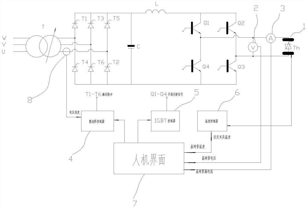
[0060] refer to figure 1 As shown, it is a test schematic diagram of the MMC power module protection thyristor breakover voltage automatic test device provided in this embodiment. The device mainly includes a power supply, a transformer T, a rectifier bridge, an IGBT full-bridge inverter, an electric heating fixture 1, and a voltmeter. 2. Ammeter 3, rectifier bridge controller 4, IGBT controller 5 and temperature controller 6.
[0061] Wherein, the power supply in this embodiment adopts U, V, W three-phase power supply, and the transformer T adopts a step-up transformer, the primary side of the transformer T is connected with the power supply, and the secondary side of the transformer T is connected with the rectifier The input terminals of the bridge are connected. Specifically, the rectifier bridge is composed of six diodes T1-T6 to output DC voltage to the IGBT full-bridge inverter; the IGBT full-bridge inverter outputs according to the control command Different voltage wa...
Embodiment 2
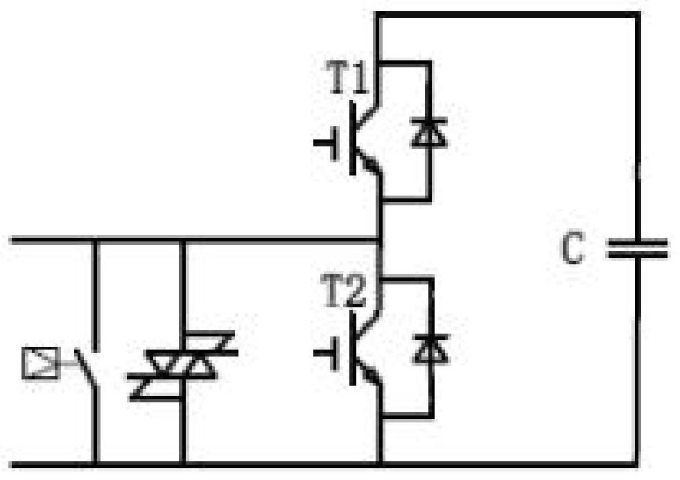
[0067] This embodiment provides a half-bridge power module protection thyristor breakover voltage testing method, the method is carried out by using the MMC power module protection thyristor breakover voltage automatic test device described in Embodiment 1, including:
[0068] Step 1: Set the maximum test voltage Vs, leakage current Is, and test temperature Ts of the thyristor Th under test on the man-machine interface;
[0069] Step 2: Install the thyristor T under test into the heating fixture and heat it to the test temperature Ts;
[0070] Step 3: Adjust the trigger angle of the rectifier bridge thyristor to 90°, so that the output voltage of the rectifier bridge is 0;
[0071] Step 4: The IGBT controller controls Q3 to keep on and Q2 to keep off;
[0072] Step 5: The IGBT controller controls Q1 to be turned on and Q4 to be turned off, keeping the set time T1;
[0073] Step 6: The IGBT controller controls Q1 to turn off, Q4 to turn on, and maintains the set time T2;
[...
Embodiment 3
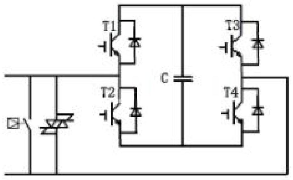
[0083] This embodiment provides a full-bridge power module protection thyristor breakover voltage testing method, the method is carried out by using the MMC power module protection thyristor breakover voltage automatic test device described in Embodiment 1, including:
[0084] Step 1: Set the maximum test voltage Vs, leakage current Is, and test temperature Ts of the thyristor Th under test on the man-machine interface;
[0085] Step 2: Install the protection thyristor T into the heating fixture and heat it to the test temperature Ts;
[0086] Step 3: Adjust the trigger angle of the rectifier bridge thyristor to 90°, so that the output voltage of the rectifier bridge is 0;
[0087] Step 4: The IGBT controller controls Q1 and Q3 to be turned on at the same time, and Q2 and Q4 to be turned off at the same time, keeping the set time T3;
[0088] Step 5: The IGBT controller controls Q1 and Q3 to be turned off at the same time, and Q2 and Q4 to be turned on at the same time, keepi...
PUM
 Abstract
Description
Claims
Application Information
 - R&D
- Intellectual Property
- Life Sciences
- Materials
- Tech Scout
- Unparalleled Data Quality
- Higher Quality Content
- 60% Fewer Hallucinations
Browse by: Latest US Patents, China's latest patents, Technical Efficacy Thesaurus, Application Domain, Technology Topic, Popular Technical Reports.
© 2025 PatSnap. All rights reserved.Legal|Privacy policy|Modern Slavery Act Transparency Statement|Sitemap|About US| Contact US: help@patsnap.com


