
Strength test device for intermediate case of aeroengine with large bypass ratio

An aero-engine and strength test technology, which is applied in the direction of measuring devices, testing of mechanical components, testing of machine/structural components, etc., can solve the problems of design and test assembly difficulties, increase test cost, and small load quantity, etc., and achieve reduced assembly workload effect

Active Publication Date: 2020-01-24
AECC SHENYANG ENGINE RES INST
View PDF8 Cites 10 Cited by
  • Summary
  • Abstract
  • Description
  • Claims
  • Application Information

AI Technical Summary

Problems solved by technology

The above-mentioned test device has the following disadvantages. Various test loads are loaded separately, and there is a lack of load synthesis and simplification. When encountering a complex load test such as an intermediate casing, it is easy to cause too many loading channels and the test device is too complicated. The test assembly is difficult, and even the loading cannot be realized due to load interference; the test device of the building block type lap is suitable for simple tests with a small number of loads and a single working condition, and when the number of test loads and working conditions is large, the load orientation should be adjusted each time , all need to readjust the bearing and loading structure, which brings a huge workload, which not only increases the test cost, but also reduces the test efficiency

Method used


Image

  • Strength test device for intermediate case of aeroengine with large bypass ratio
  • Strength test device for intermediate case of aeroengine with large bypass ratio
  • Strength test device for intermediate case of aeroengine with large bypass ratio

Examples


Embodiment Construction

[0055] In order to make the purpose, technical solution and advantages of the application more clear, the technical solution in the embodiment of the application will be described in more detail below in conjunction with the drawings in the embodiment of the application. In the drawings, the same or similar reference numerals denote the same or similar elements or elements having the same or similar functions throughout. The described embodiments are some, but not all, embodiments of the application. The embodiments described below by referring to the figures are exemplary, and are intended to explain the present application, and should not be construed as limiting the present application. Based on the embodiments in this application, all other embodiments obtained by persons of ordinary skill in the art without creative efforts fall within the protection scope of this application. Embodiments of the present application will be described in detail below in conjunction with th...


PUM


Abstract

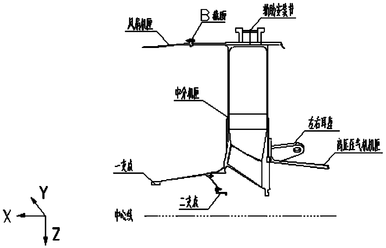
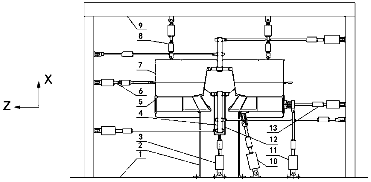
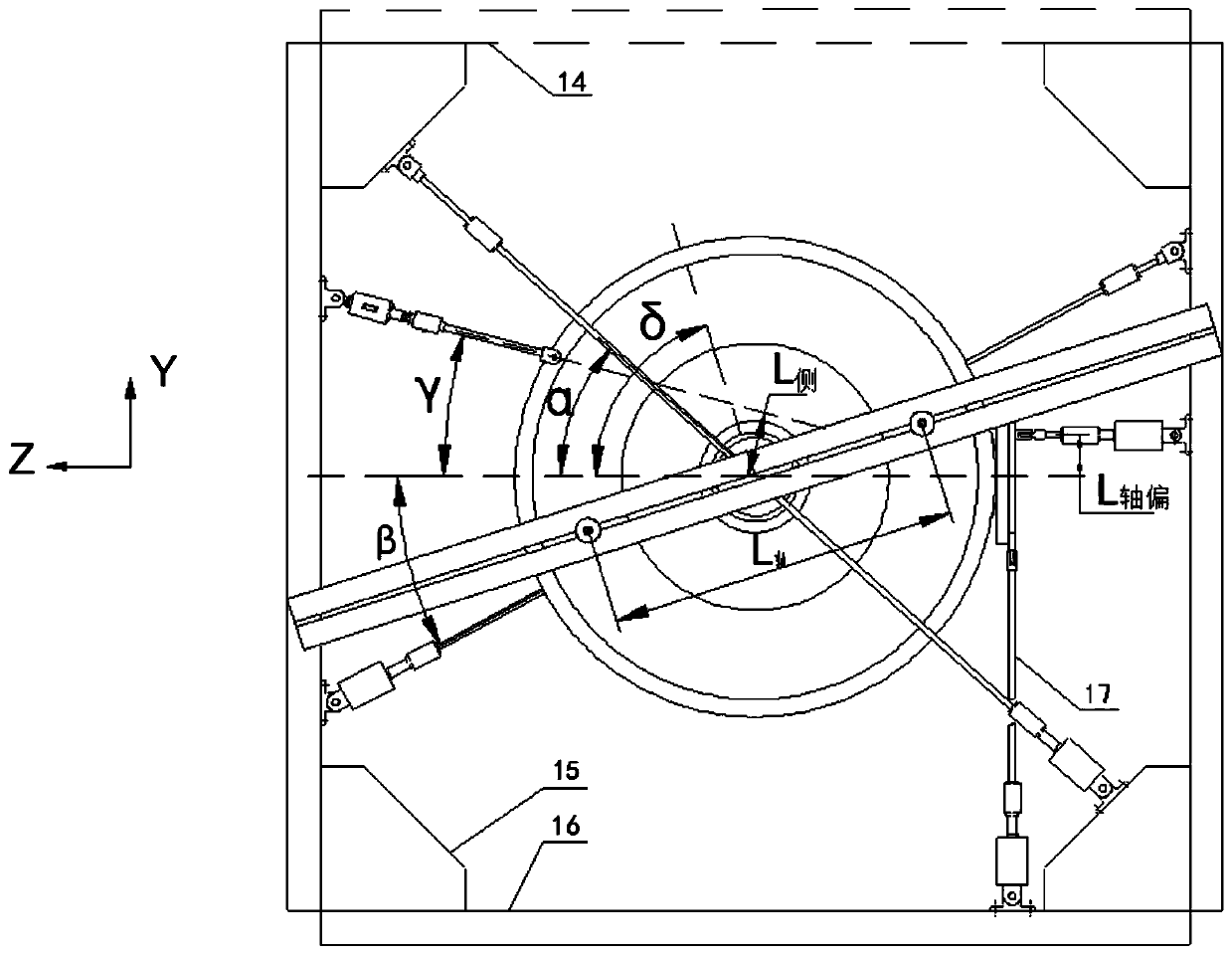
The invention belongs to the field of aviation test devices, and particularly relates to a strength test device for an intermediate case of an aeroengine with a large bypass ratio. The strength test device comprises an intermediate case test piece, a bearing assembly, a simulation case and a loading assembly, wherein an auxiliary installation joint, a B-section installation edge, a main installation joint lug set, a first support point and a second support point are arranged at an outer side of the intermediate case test piece, a bottom end of a triangular vertical post of the bearing assemblyis fixedly arranged on a foundation platform, a bearing beam and a bearing wall are arranged on the triangular vertical post, a top-end cross beam is arrange on the bearing beam and / or the triangularvertical beam and / or the bearing wall, a bottom end of a simulation high-pressure compressor case is arranged on the foundation platform, a top end is connected with a bottom end of the intermediatecase test piece, a bottom end of a simulation fan case is in bolt connection with the B-section installation edge, the loading assembly is arranged on the bearing assembly and is used for loading thetwo support points of the intermediate case test piece, a B section, the main installation joint lug seat and the auxiliary installation joint. By the strength test device, the workload can be reduced, and the strength test device is high in universality.

Description

technical field [0001] The application belongs to the field of aviation test devices, and in particular relates to a test device for the strength of an intermediate casing of an aero-engine with a large bypass ratio. Background technique [0002] As an important load-bearing part of an aero-engine, the intermediate casing is subject to the most complex mechanical and aerodynamic loads. Once it fails, it will endanger flight safety, so it must be assessed for strength. [0003] In the casing test in the prior art, various test loads are loaded separately in the loading aspect, and the building block type lap joint is used in the device aspect, and a special design structure is required for the casing with a specific structure. The test device of the above-mentioned form has the following disadvantages. Various test loads are loaded separately, and there is a lack of synthesis and simplification of the load. When encountering a complex load test such as an intermediate casing,...

Claims


Application Information

Patent Timeline
Patent Type & Authority Applications(China)
IPC IPC(8): G01M13/00
CPCG01M13/00
Inventor 魏洪吉于云飞刘向田
Owner AECC SHENYANG ENGINE RES INST
Learn More