
Beam device used for installing ground test equipment

A technology for ground testing equipment and beams, applied in the field of vehicles, can solve the problems of single function, affecting the overall spatial arrangement, complex structure of the outrigger beam, etc., to achieve the effect of facilitating processing and assembly, improving space utilization, and facilitating replacement and maintenance.

Active Publication Date: 2020-01-24
SPECIAL VEHICLE TECH CENT OF HUBEI AEROSPACE TECH RES INST
View PDF4 Cites 0 Cited by
  • Summary
  • Abstract
  • Description
  • Claims
  • Application Information

AI Technical Summary

Problems solved by technology

[0003] The invention provides a crossbeam device for installing ground testing equipment, which solves the technical problems in the prior art that the outrigger crossbeam has a complex structure and single function, and affects the overall space layout, and achieves a simple structure, easy processing and assembly, and satisfies the ground. Strengthen the strength requirements of the measurement equipment, realize the integrated installation of the ground strength measurement equipment, improve the space utilization rate, and facilitate the technical effect of replacement and maintenance

Method used


Image

  • Beam device used for installing ground test equipment
  • Beam device used for installing ground test equipment
  • Beam device used for installing ground test equipment

Examples


Embodiment

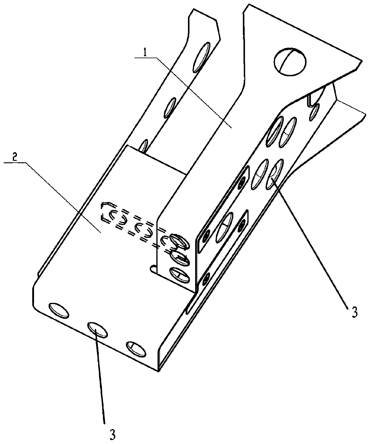
[0028] figure 1 It is a structural schematic diagram of a beam device for installing ground testing equipment in an embodiment of the present invention, such as figure 1 Shown:

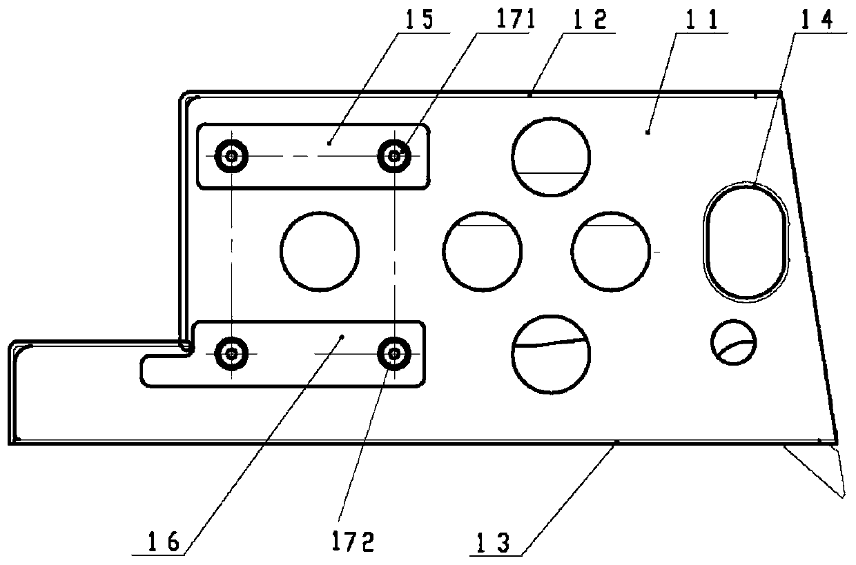
[0029] The beam device for installing ground testing equipment includes: a beam body 1, the beam body 1 includes: a bottom plate 13; a first vertical plate 11, the first vertical plate 11 is vertically arranged with the bottom plate 13, and One side of the first vertical plate 11 is flush with the edge of the bottom plate 13; the second vertical plate is arranged in parallel with the first vertical plate 11; the cover plate 12, the The cover plate 12 is fixedly connected with the first vertical plate 11 and the end of the second vertical plate away from the bottom plate 13, and is formed by the bottom plate 13, the first vertical plate 11, the second vertical plate and the cover plate 12. A storage space.

[0030] Further, a plurality of drainage holes are opened on the bottom plate 13 .

[0031] ...


PUM


Abstract

The invention discloses a beam device used for installing ground test equipment, and belongs to the technical field of vehicles. The beam device comprises a beam body, wherein the beam body comprisesa bottom plate, a first vertical plate, a second vertical plate, a cover plate and a platform support. The first vertical plate is perpendicular to the bottom plate, and one side face of the first vertical plate is flush with the edge of the bottom plate; the second vertical plate is parallel to the first vertical plate; the cover plate is fixedly connected with the ends, away from the bottom plate, of the first and second vertical plates, and a containing space is formed by the bottom plate, the first vertical plate, the second vertical plate and the cover plate; the platform support is belowthe beam body and is fixedly connected with the beam body. In this way, the beam device has the advantages that the structure is simple, convenience is brought to processing and assembly, the strength requirements of the ground test equipment are met, integrated installation of the ground test equipment is achieved, the space utilization rate is increased, and replacement and maintenance are facilitated.

Description

technical field [0001] The invention relates to the technical field of vehicles, in particular to a beam device for installing ground testing equipment. Background technique [0002] At present, some ultra-heavy off-road vehicle chassis need to install ground strength measuring equipment. At this time, the load-bearing structure is required to have a large load-bearing capacity, sufficient strength, small space occupation, and lightweight design. In the existing special vehicle chassis, there are front and rear outrigger beams etc. commonly used in the structure used for top loading, but the existing outrigger beam structure often has the following problems: first: the outrigger beam includes the inner side beam of the outrigger 1. The outer beam of the outrigger has a complex structure and a single function; second: the upper-mounted beam outrigger is generally installed on the outer end of the beam, the frame is subjected to a large moment, and the width of the chassis is ...

Claims


Application Information

Patent Timeline
IPC IPC(8): B62D21/09B60R11/00
CPCB60R11/00B62D21/09
Inventor 刘志强秦初荣王晨旭彭一鸣
Owner SPECIAL VEHICLE TECH CENT OF HUBEI AEROSPACE TECH RES INST
Learn More