
Heat dissipation device for new energy battery

A heat dissipation device and new energy technology, applied in the direction of secondary batteries, battery pack components, circuits, etc., can solve the problems of new energy battery damage, high temperature, shortened charge and discharge cycle life, etc., to buffer the impact force, use Convenience and protection from damage

Inactive Publication Date: 2020-01-17
合肥鸿叶紫新能源有限公司
View PDF0 Cites 12 Cited by
  • Summary
  • Abstract
  • Description
  • Claims
  • Application Information

AI Technical Summary

Problems solved by technology

[0002] Now new energy batteries have gradually become the power source of many mechanical structures or machines. The protection and heat dissipation functions of new energy batteries are the key to the safe operation of mechanical structures or machines. However, we often see that when new energy batteries are used , will generate a lot of heat. If no relevant measures are taken to dissipate heat, the power supply efficiency of the new energy battery will decrease, and the cycle life of charge and discharge will be shortened sharply. However, the current new energy battery is only on the ordinary protective cover in terms of heat dissipation. Opening cooling holes cannot effectively solve the problem of overheating during the power supply process; in addition, in terms of protection, the new energy battery is simply fixed at a specific position without a buffer function, which may easily cause the new energy battery to be affected by strong damaged by impact

Method used


Image

  • Heat dissipation device for new energy battery
  • Heat dissipation device for new energy battery

Examples


Embodiment

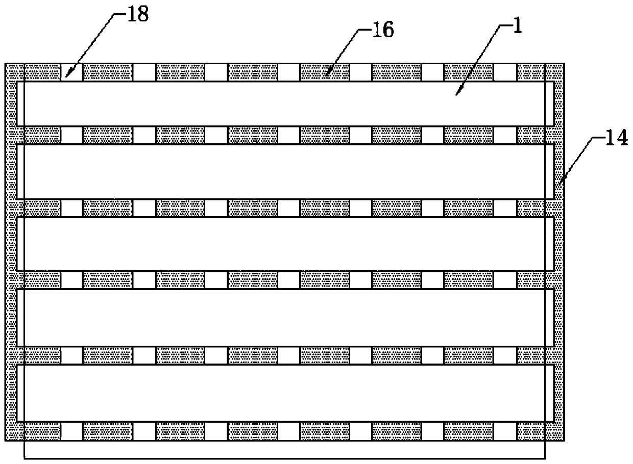
[0021] Example: such as Figure 1-2 As shown, a heat dissipation device for new energy batteries includes a battery shield 1 and a heat dissipation system. The battery shield 1 is provided with a number of adjustable abutment shafts 3 connected to the support plate 2, and a number of rolling bearings are embedded in the support plate 2. Small ball 4, and the bottom side of the support plate 2 is connected with the cylinder 6 through the telescopic shaft 5, the cylinder 6 is fixedly installed on the inner side of the battery shield 1 and is located below the adjustment abutment shaft 3, and the bottom of the cylinder 6 is set There is a function adjustment cavity 7, and a push plate 8 is installed in the function adjustment cavity 7, a side plate 10 fixedly connected to the battery bottom cavity 9 at one end, a thermal expansion air bag 11 movably connected to the push plate 8 at the other end, and a baffle 12, a baffle 12 The two ends of the battery are respectively connected ...


PUM


Abstract

The invention discloses a heat dissipation device for a new energy battery. The device comprises a battery protection cover and a heat dissipation system, a plurality of adjusting abutting shafts connected with a supporting plate are arranged on the battery protective cover; a plurality of small rolling balls are embedded in the supporting plate; the side edge of the bottom of the supporting plateis connected with an air cylinder through a telescopic shaft. The air cylinder is fixedly installed on the inner side edge of the battery protective cover and located below the adjusting abutting shaft, a function adjusting cavity is formed below the air cylinder, a push plate, a thermal expansion air bag and a baffle are installed in the function adjusting cavity, and the two ends of the baffleare connected with a side plate of the battery bottom containing cavity and the inner side wall of the battery protective cover correspondingly; the heat dissipation system comprises fans installed onthe two side edges of the exterior of the battery protection cover, air pipes communicating with the fans and the air collecting pipes and a plurality of heat dissipation air outlet pipes, the multiple heat dissipation air outlet pipes are evenly embedded in the periphery of the interior of the battery protection cover and communicate with the air collecting pipes through connectors, and a plurality of ventilation holes are formed in the heat dissipation air outlet pipes.

Description

technical field [0001] The invention relates to the technical field of new energy batteries, in particular to a heat dissipation device for new energy batteries. Background technique [0002] Now new energy batteries have gradually become the power source of many mechanical structures or machines. The protection and heat dissipation functions of new energy batteries are the key to the safe operation of mechanical structures or machines. However, we often see that when new energy batteries are used , will generate a lot of heat. If no relevant measures are taken to dissipate heat, the power supply efficiency of the new energy battery will decrease, and the cycle life of charge and discharge will be shortened sharply. However, the current new energy battery is only on the ordinary protective cover in terms of heat dissipation. Opening cooling holes cannot effectively solve the problem of overheating during the power supply process; in addition, in terms of protection, the new ...

Claims


Application Information

Patent Timeline
Patent Type & Authority Applications(China)
IPC IPC(8): H01M2/10H01M10/613H01M10/6556H01M10/6563
CPCH01M10/613H01M10/6556H01M10/6563H01M50/20Y02E60/10
Inventor 孟艳
Owner 合肥鸿叶紫新能源有限公司
Learn More