Mobile cooling device for power cabinet

A heat dissipation device, mobile technology, applied in substation/power distribution device shell, cooling/ventilation of substation/switchgear, details of substation/switch layout, etc., can solve the problem of reducing the heat dissipation of power cabinets and reducing the working efficiency of solar panels , power equipment aging and other issues, to reduce power consumption, prolong service life and ensure stability

Active Publication Date: 2019-08-30
PINGYIN POWER SUPPLY CO OF STATE GRID SHANDONG ELECTRIC POWER CO +1
View PDF14 Cites 9 Cited by
  • Summary
  • Abstract
  • Description
  • Claims
  • Application Information

AI Technical Summary

Problems solved by technology

[0002] With the rapid development of power technology, outdoor power cabinets, power distribution cabinets and other cabinets for the installation of various electrical components have also been fully developed. Power cabinets are a commonly used power infrastructure. The power equipment will generate a lot of heat when the power equipment is running, and the heat needs to be discharged from the cabinet in time, otherwise the heat will accumulate, which will easily cause the aging of the power equipment, and even the risk of explosion
[0003] After searching, the Chinese invention patent with the application number 201710629344.2 discloses a power cabinet that is convenient for dehumidification and heat dissipation, and specifically discloses that it includes the main body of the power cabinet. A battery is installed on the right side of the battery. A rotating motor is connected to the right end of the battery, and a motor bearing is installed inside the rotating motor. A belt is arranged outside the motor bearing, and a fan bearing is connected inside the right side of the belt. The middle part of the top of the power cabinet main body is installed There is a panel pole, and a solar panel is installed on the top of the panel pole. A heat dissipation chamber is arranged under the main body of the power cabinet, and an air outlet is

Method used


Image

  • Mobile cooling device for power cabinet
  • Mobile cooling device for power cabinet
  • Mobile cooling device for power cabinet

Examples


Embodiment 1

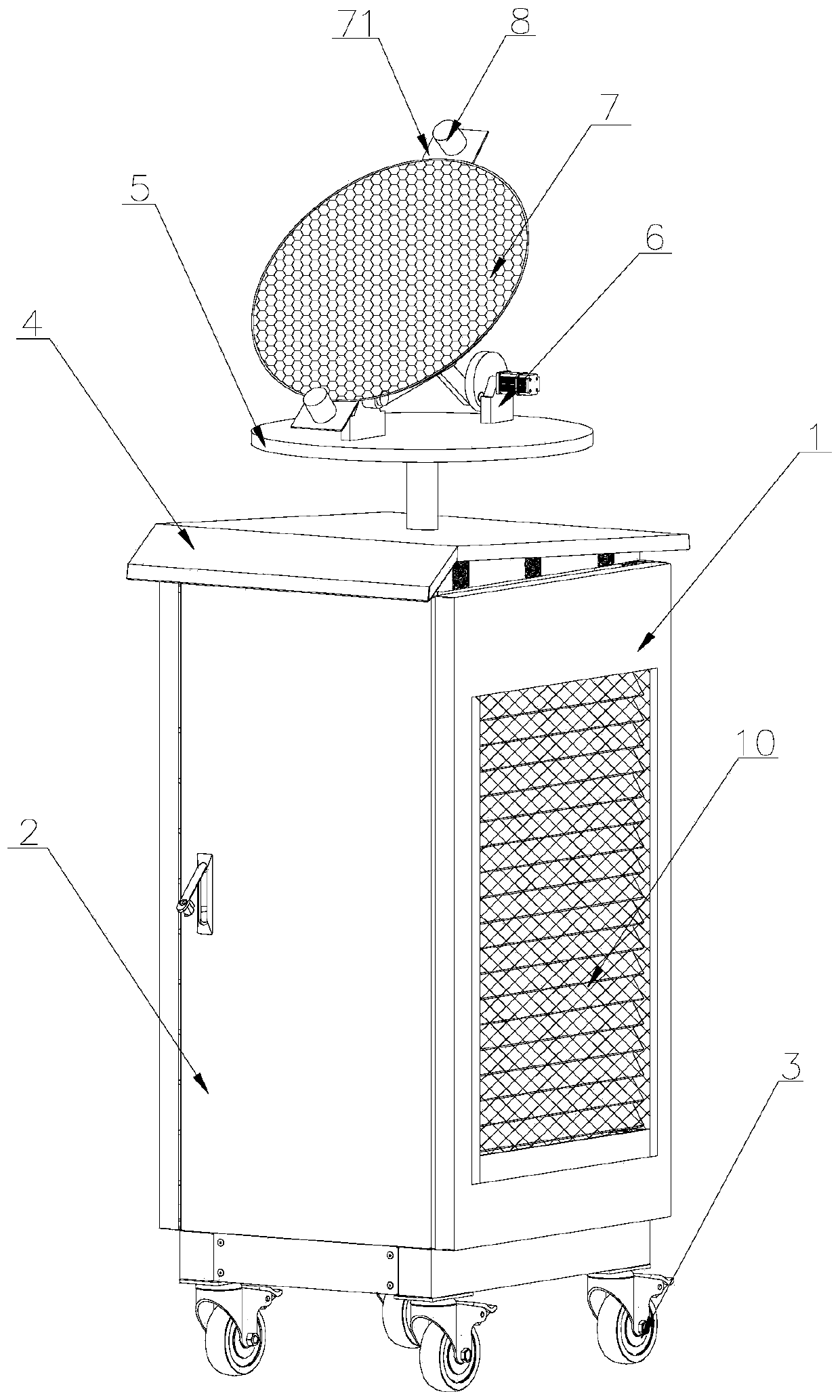
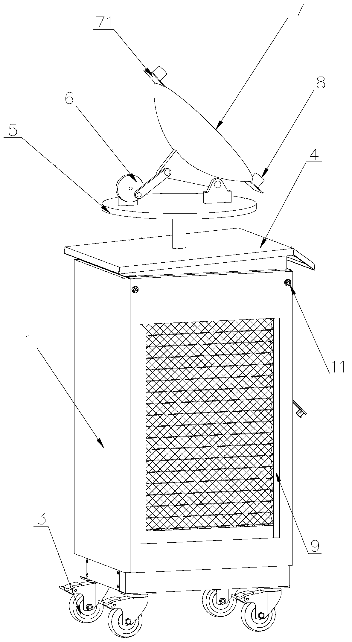
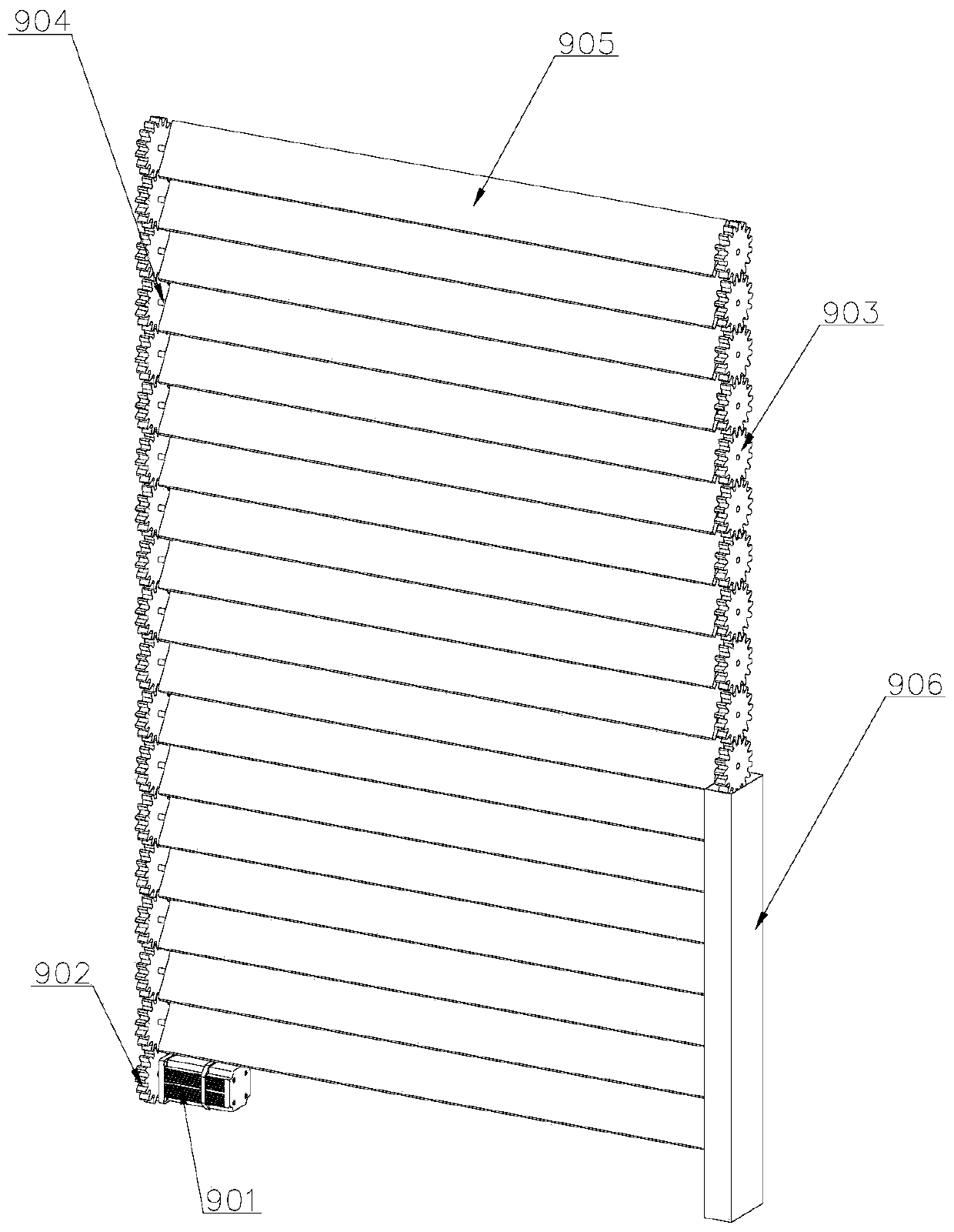
[0038] Such as Figure 1-7 As shown, a mobile cooling device for power cabinets, including a box body 1, a box door 2, a walking wheel 3, an angle adjustment device 5, a height adjustment device 6, a solar panel 7, a light sensor 8, a shutter device 9, a top plate 12. Controller 16, storage battery 17, the box door 2 is set on the box body 1 and is hinged with the box body 1, and the walking wheels 3 are fixedly arranged on the bottom of the box body 1 to facilitate the movement of the power cabinet. The louver device 9 is arranged on both sides of the box body 1, and the louver device 9 is fixedly installed on the side wall of the box body 1, and the electric equipment installed inside the box body 1 is ventilated and dissipated through the louver device 9, so as to ensure that the power equipment is in operation. stability, the top plate 12 is arranged on the top of the box body 1, the angle adjustment device 5, the controller 16, and the storage battery 17 are all arranged ...

Embodiment 2

[0048] Such as Figure 8 As shown, the difference from Embodiment 1 is that the height adjustment device 6 includes a second drive motor 601, a second support 606, a second connecting plate 607, a screw rod 608, and a sleeve 609. The second support 606 is fixedly installed above the supporting plate 505, the second connecting plate 607 is arranged on the bottom side of the solar panel 7, the second connecting plate 607 is hinged with the second support 606, and the second driving motor 601 is fixedly arranged on the support Above the plate 505, the screw rod 608 is arranged at the end of the output shaft of the second driving motor 601, the sleeve 609 is arranged outside the screw rod 608, one end of the sleeve 609 is fixedly connected with the bottom of the solar panel 7, and the inside of the sleeve 609 is arranged There is a screw thread matched with the screw rod 608, the second drive motor 601 drives the screw rod 608 to rotate forward and backward, and the connecting sle...

Embodiment 3

[0050] Such as Figure 9 As shown, the difference from Embodiment 1 is that the height adjustment device 6 includes a second support 606, a second connecting plate 607, and a telescopic rod 610, and the second support 606 is fixedly installed above the support plate 505, so The second connection plate 607 is arranged on one side of the bottom of the solar panel 7, and the second connection plate 607 is hinged to the second support 606. One end of the telescopic rod 610 is fixed above the support plate 505, and the other end is connected to the bottom of the solar panel 7. connection, the solar panel 7 is driven to move through the telescopic rod 610, and the second connecting plate 607 rotates around the second support 606, so that the height of the solar panel 7 is adjusted.


PUM


Abstract

The invention discloses a mobile cooling device for a power cabinet, comprising a box body, a box door, a walking wheel, an angle adjusting device, a height adjusting device, a solar panel, a light sensor, louver devices, a top plate, a controller, and a battery. The box door is disposed on the box body and is hinged to the box body. The walking wheel is fixedly disposed on the bottom of the box body. The louver devices are disposed on the two sides of the box body and are fixedly mounted on the side walls of the box body. The solar panel moves with the sun and can capture the solar energy inall directions in real time so as to operate in an optimal state. Thus, the working efficiency of the solar panel is ensured. The louver devices on both sides of the box body ventilates the power cabinet to dissipates the heat generated by the power equipment inside the power cabinet in operation so as to achieve a cooling effect while reducing the consumption of electric energy.

Description

technical field [0001] The invention belongs to the technical field of electric power equipment, and in particular relates to a mobile cooling device for a power cabinet. Background technique [0002] With the rapid development of power technology, outdoor power cabinets, power distribution cabinets and other cabinets for the installation of various electrical components have also been fully developed. Power cabinets are a commonly used power infrastructure. The power equipment will generate a lot of heat when the power equipment is running, and the heat needs to be discharged from the cabinet in time, otherwise the heat will accumulate, which will easily cause the aging of the power equipment, and even the risk of explosion. [0003] After searching, the Chinese invention patent with the application number 201710629344.2 discloses a power cabinet that is convenient for dehumidification and heat dissipation, and specifically discloses that it includes the main body of the po...

Claims


Application Information

Patent Timeline
IPC IPC(8): H02B1/56H02B1/28H02S20/32
CPCH02B1/28H02B1/565H02S20/32Y02E10/50
Inventor 张文杨涛袁晨魏文峰张来张凯
Owner PINGYIN POWER SUPPLY CO OF STATE GRID SHANDONG ELECTRIC POWER CO
Why Eureka
Try Eureka