
An event-triggered position tracking control method for permanent magnet synchronous motors

A permanent magnet synchronous motor and event-triggered technology, applied in motor generator control, motor control, AC motor control, etc., can solve matching and non-matching disturbances, permanent magnet synchronous motors cannot be modeled accurately, and problems such as limited wide resources problem, to achieve the effect of solving causal contradictions, improving anti-interference ability, and saving network bandwidth resources

Active Publication Date: 2021-07-23
SOUTH CHINA UNIV OF TECH +1
View PDF3 Cites 0 Cited by
  • Summary
  • Abstract
  • Description
  • Claims
  • Application Information

AI Technical Summary

Problems solved by technology

Aiming at the problem that the permanent magnet synchronous motor cannot be accurately modeled, this method uses the universal approximation theorem of the neural network, combined with the inverse design method to realize the adaptive neural network control; for the problem of limited network bandwidth resources, the method is between the controller and the actuator The network channel introduces an event trigger mechanism to reduce unnecessary signal transmission and achieve the purpose of effectively saving network bandwidth resources; in view of the problem of matching and non-matching disturbances in the permanent magnet synchronous motor control system, this method uses a disturbance observer to estimate the disturbance. Combined with the reverse push control method, the feedforward compensator is designed to improve the anti-interference ability of the system

Method used


Image

  • An event-triggered position tracking control method for permanent magnet synchronous motors
  • An event-triggered position tracking control method for permanent magnet synchronous motors
  • An event-triggered position tracking control method for permanent magnet synchronous motors

Examples


Embodiment

[0095] Such as figure 1 , figure 2 As shown, this embodiment provides an event-based permanent magnet synchronous motor position tracking control method, and its detailed implementation process includes:

[0096] Step 1. Establish the dynamic model of the permanent magnet synchronous motor:

[0097]

[0098]

[0099]

[0100]

[0101] the y 1 = θ

[0102] the y 2 = i d

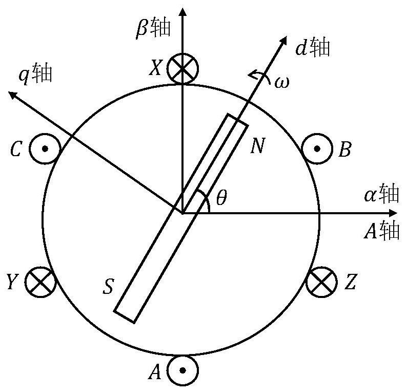
[0103] Among them, θ, ω, i q and i d is the state of the system, which are the rotor position of the motor, the rotor angular velocity, the q-axis current and the d-axis current; u q and u d is the system input, respectively q-axis voltage and d-axis voltage; y 1 and y 2 are the system output, respectively the rotor position and the d-axis current; J,n p ,B,L,R s , T L and Φ are system parameters, which are moment of inertia, extreme value pair, viscous friction, stator inductance, stator resistance, load torque and magnetic flux, respectively; Δf ω (ω),Δf q (ω,i q ,i d ) and Δf d...


PUM


Abstract

The invention discloses an event-triggered permanent magnet synchronous motor position tracking control method, comprising the following steps: establishing a dynamic model of the permanent magnet synchronous motor and an expected tracking trajectory; discretizing the permanent magnet synchronous motor system; designing a controller that acts on the The event triggering mechanism of the network channel between the actuator and the controller; the design of an adaptive neural network controller based on event triggering; the design of a disturbance observer; the design of a feedforward compensator that compensates for matching and non-matching disturbances. The method designed in the present invention can not only obtain good position tracking performance and anti-interference ability, but also extend the traditional time-triggered control mode of permanent magnet synchronous motor to event-triggered control mode, effectively saving the networked control system of permanent magnet synchronous motor Resources such as network bandwidth, computing and energy enable the system to operate normally even under network congestion.

Description

technical field [0001] The invention relates to the technical field of position tracking control of permanent magnet synchronous motors, in particular to an event-triggered based position tracking control method of permanent magnet synchronous motors. Background technique [0002] Permanent magnet synchronous motor is a motor in which the rotor excited by permanent magnets rotates synchronously with the stator space magnetic field. Compared with traditional electrically excited motors and induction motors, permanent magnet synchronous motors have significant advantages such as simple structure, small size, high efficiency, and high power density, and have been used in many applications in the fields of position control, drive traction, and high-efficiency power output. In addition, introducing the network into the control system to design a networked control system has changed the traditional point-to-point control method, which has broad development prospects and research s...

Claims


Application Information

Patent Timeline
Patent Type & Authority Patents(China)
IPC IPC(8): G06F30/20G06N3/04H02P6/34H02P21/00H02P21/13H02P23/00H02P23/12H02P25/022H04L12/801
CPCG06N3/04H02P21/0014H02P21/13H02P23/0018H02P23/12H02P25/022H02P2207/05H04L47/10H02P6/34
Inventor 王敏黄锐鹏戴诗陆杨辰光
Owner SOUTH CHINA UNIV OF TECH
Learn More