Hyper-beam forming method based on near-field focusing

A near-field focusing and super-beam technology, which is applied in the direction of sound wave re-radiation, radio wave measurement systems, instruments, etc., can solve problems such as imaging blur, and achieve the effects of improving detection performance, simple structure, and easy implementation

Pending Publication Date: 2020-01-14
HAIYING ENTERPRISE GROUP
View PDF5 Cites 6 Cited by
  • Summary
  • Abstract
  • Description
  • Claims
  • Application Information

AI Technical Summary

Problems solved by technology

[0003] The purpose of the present invention is to provide a super-beamforming method based on near-field focusing to solve the problem of blurred imaging in the near-field working area of ​​traditional beamforming

Method used


Image

  • Hyper-beam forming method based on near-field focusing
  • Hyper-beam forming method based on near-field focusing
  • Hyper-beam forming method based on near-field focusing

Examples


Embodiment 1

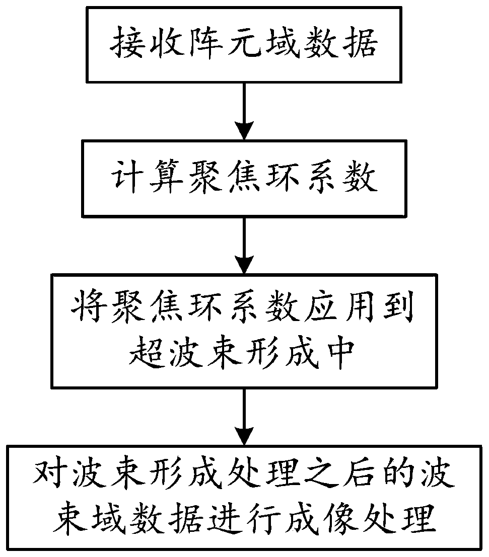
[0048] The present invention provides a super-beamforming method based on near-field focusing, the process of which is as follows figure 1 shown, including:

[0049] Receive array field data;

[0050] Calculate the focus ring coefficient;

[0051] Apply focus ring coefficients to hyperbeamforming;

[0052] Imaging processing is performed on the beam domain data after the beamforming processing.

[0053] Specifically, Step 1: Receive data:

[0054] Receive array field data;

[0055] Step 2: Calculate the focus ring coefficient:

[0056] The near-field conditions are:

[0057] Among them, L is the effective array length of the base array, λ is the wavelength, and D is the distance in the near-field range.

[0058] Acoustic focusing phase shifting The phase shift of beamforming is calculated according to the law of spherical waves. Acoustic focusing on the sound waves emitted from a certain point in space can form left and right array acoustic focusing, such as figure ...


PUM


Abstract

The invention belongs to the technical field of sonar signal processing, and discloses a hyper-beam forming method based on near-field focusing. The method comprises the following steps: receiving element space data; calculating a focusing ring coefficient; applying the focusing ring coefficient in hyper-beam forming; and carrying out imaging processing on beam space data obtained after beam forming processing. The method disclosed by the invention has the advantages that a hyper-beam achieves a narrow main lobe and a low sidelobe, so that the detection performance of a sonar system can be effectively improved, the false alarm probability can be reduced, and the estimation precision for a target orientation can be increased; and the segment focusing hyper-beam forming technology is adoptedfor phase focusing compensation within a near-field range, so that the problem of image blurring caused by phase mismatching can be solved.

Description

technical field [0001] The invention relates to the technical field of sonar signal processing, in particular to a super beam forming method based on near-field focusing. Background technique [0002] High-frequency multi-beam sonar is an important instrument for marine target detection at present, and it is mainly used in the detection, positioning and classification of short-distance small targets in the ocean. However, in the near-field working area of ​​the image sonar, there are problems such as imaging blur, which seriously affects the working performance of the equipment. This is because the traditional beamforming method is based on the assumption of plane waves, without focus compensation in the near-field range, resulting in phase mismatch, the main lobe of the beam will become wider, and the side lobes will increase, resulting in a decrease in azimuth resolution, resulting in sonar Severe deterioration of image performance. At the same time, the traditional conv...

Claims


Application Information

Patent Timeline
Patent Type & Authority Applications(China)
IPC IPC(8): G01S15/89G01S7/526
CPCG01S15/89G01S7/526
Inventor 王升凤夏梦月费玉杰
Owner HAIYING ENTERPRISE GROUP
Why Eureka
Try Eureka