Wood industry plate drying device

A drying device and drying device technology, applied in the direction of drying, drying machine, drying gas arrangement, etc., can solve the problems of low energy saving, unsatisfactory drying effect, small lifting work, etc., and achieve the effect of strong energy saving

Inactive Publication Date: 2020-01-14
江苏傲森博林家具有限公司
View PDF6 Cites 3 Cited by
  • Summary
  • Abstract
  • Description
  • Claims
  • Application Information

AI Technical Summary

Problems solved by technology

The labor intensity is high, and batch transportation cannot be realized, which makes the work efficiency relatively low. In addition, in the existing drying box, the drying heating area is limited and uneven, resulting in unsatisfactory drying effect
[0003] In the Chinese utility model patent document whose publication number is CN208332898U, a kind of plate drying device for wood industry is disclosed. The hot air can evenly and multi-directionally dry the two sides of the board at the same time, but the hot air after drying cannot be recycled, resulting in large heat loss and low energy saving

Method used


Image

  • Wood industry plate drying device
  • Wood industry plate drying device
  • Wood industry plate drying device

Examples


Embodiment 1

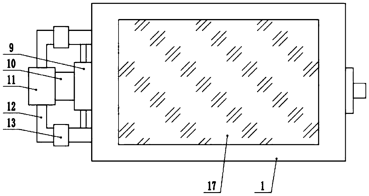
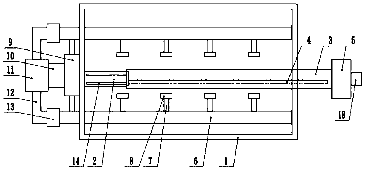
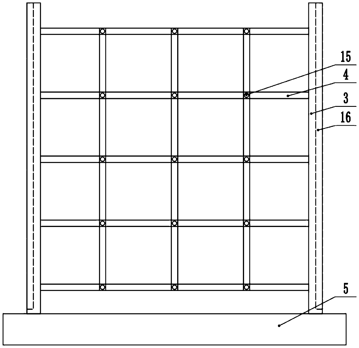
[0024] see Figure 1-3 , a wood panel drying device, comprising a drying box 1, the interior of the drying box 1 is provided with a drying mechanism and a plate placement mechanism, the outside of the drying box 1 is provided with a circulation drying mechanism, and the panel The placement mechanism includes fixed side plates 2 fixedly arranged on both sides of the inside of the drying box 1, a placement frame 4 is arranged between the two fixed side plates 2, and both sides of the placement frame 4 are fixedly connected to the sliding side plates 3. The ends of the side plates 3 are fixedly connected to the end plates 5, and the drying mechanism includes a return air pipe 6 and a hot air pipe arranged in the drying box 1. The end of the hot air pipe is fixedly provided with an exhaust head 8, and the return air There is a return air hole on the pipe 6, and the circulation drying mechanism includes a shunt cover 9 arranged at one end of the drying box 1, the shunt cover 9 is f...

Embodiment 2

[0027] see Figure 1-3 , the other content of this embodiment is the same as that of Embodiment 1, the difference is that a plurality of support blocks 15 are fixedly arranged on the placement frame 4, and one end of the end plate 5 away from the sliding side plate 3 is fixedly connected to a handle 18, The front side of the drying box 1 is provided with a viewing window 17 .

[0028] The present invention can conveniently move the wooden boards into the drying box 1 by setting the board placement mechanism, can dry the boards by setting the drying mechanism, and can dry the hot and humid air in the drying box 1 by setting the drying device 11 Drying can realize the recycling of hot air, which is highly energy-saving.


PUM


Abstract

The invention discloses a wood industry plate drying device, and relates to the technical field of wood industry processing. The device comprises a drying box, wherein a drying mechanism and a plate placing mechanism are arranged in the drying box, and a circulation drying mechanism is arranged outside the drying box; the plate placing mechanism comprises fixed side plates fixedly arranged on thetwo sides of the interior of the drying box, and a placement rack is arranged between the two fixed side plates; sliding side plates are fixedly connected to the two sides of the placement rack, and the end parts of the sliding side plates are fixedly connected with an end plate; and the drying mechanism comprises an air return pipe and a hot air pipe arranged in the drying box, and the end part of the hot air pipe is fixedly provided with an air exhaust head. According to the drying device, the wood industry board can be conveniently moved into the drying box through arranging the plate placing mechanism, the plate can be dried through arranging the drying mechanism, and wet hot air in the drying box can be dried through arranging the drying device, so that cyclic utilization of the hotair is achieved, and the energy saving performance is high.

Description

technical field [0001] The invention relates to the technical field of wood processing, in particular to a drying device for wood boards. Background technique [0002] After the board is processed by the wood board making machine, in order to make the painted surface brighter, drying treatment is required. Most of the existing board drying treatment is to move the board into the drying box for drying by workers. The labor intensity is high, and batch transportation cannot be realized, which makes the work efficiency relatively low. In addition, in the existing drying box, the drying heating area is limited and uneven, resulting in unsatisfactory drying effect. [0003] In the Chinese utility model patent document whose publication number is CN208332898U, a kind of plate drying device for wood industry is disclosed. The hot air can evenly and multi-directionally dry the two sides of the board at the same time, but the hot air after drying cannot be recycled, resulting in lar...

Claims


Application Information

Patent Timeline
Patent Type & Authority Applications(China)
IPC IPC(8): F26B5/16F26B9/10F26B21/00
CPCF26B5/16F26B9/10F26B21/001
Inventor 钱卫东
Owner 江苏傲森博林家具有限公司
Why Eureka
Try Eureka