Concrete water storage device with water level indicating function

A technology of water storage device and water level indication, applied in water supply device, configuration of water supply pool, large-capacity bulk material storage, etc. The effect of strengthening structural strength and reducing physical expenditure

Pending Publication Date: 2020-01-14
重庆聚钡混凝土有限公司
View PDF0 Cites 0 Cited by
  • Summary
  • Abstract
  • Description
  • Claims
  • Application Information

AI Technical Summary

Problems solved by technology

[0002] As we all know, a large amount of concrete needs to be used in the construction process of construction projects. In order to meet the needs of use, many construction sites use on-site mixing to supply concrete. When mixing concrete, a large amount of water is consumed. Under the existing technical conditions, some concrete The mixing work is carried out on a taller building, which makes water supply more difficult. Water supply through manual water supply greatly increases the physical exertion of the staff and seriously affects work efficiency. The structure of the existing water storage device is too simple , the structural strength is low, a large amount of water storage is easy to cause damage, and it is not convenient to observe the remaining amount of water storage, and the existing water storage device relies on ordinary water pumps for water supply, and the lift of ordinary water pumps is limited, which is difficult to meet the use of high-altitude construction. , with in-depth research on the above problems, this case arises

Method used


Image

  • Concrete water storage device with water level indicating function
  • Concrete water storage device with water level indicating function
  • Concrete water storage device with water level indicating function

Examples


Embodiment

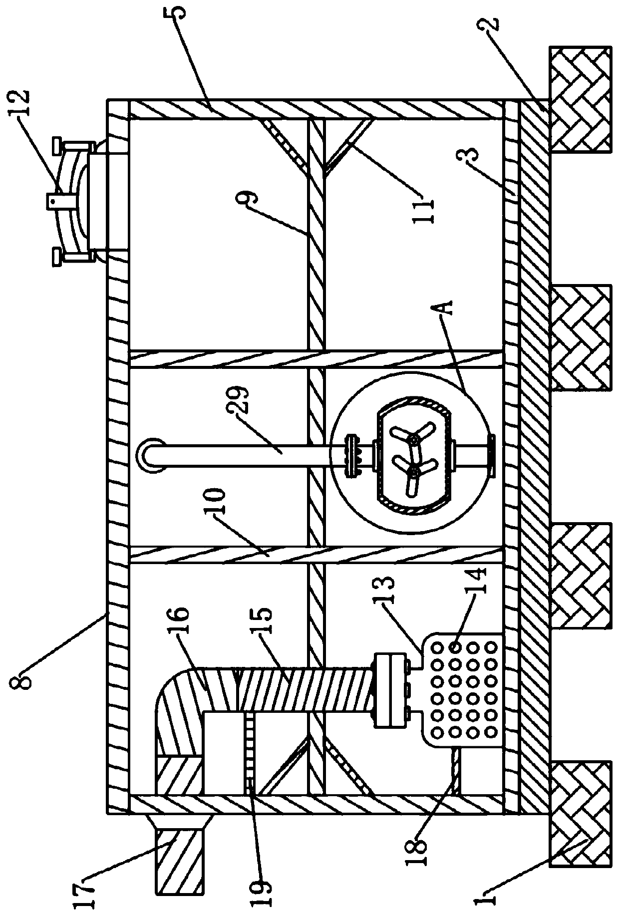
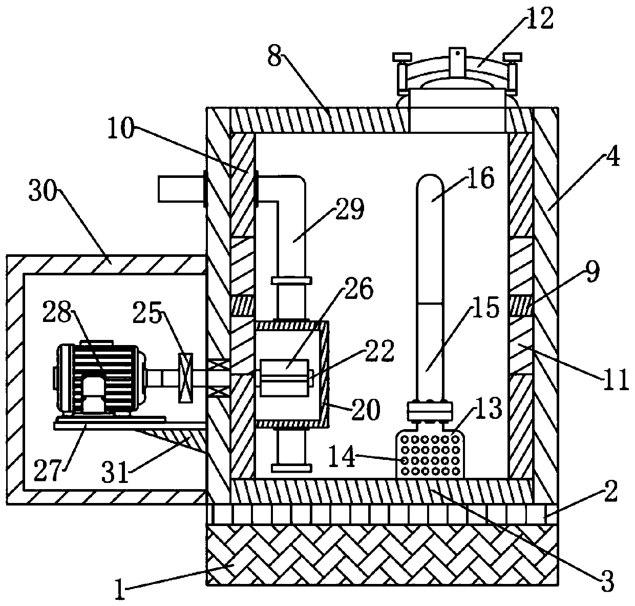
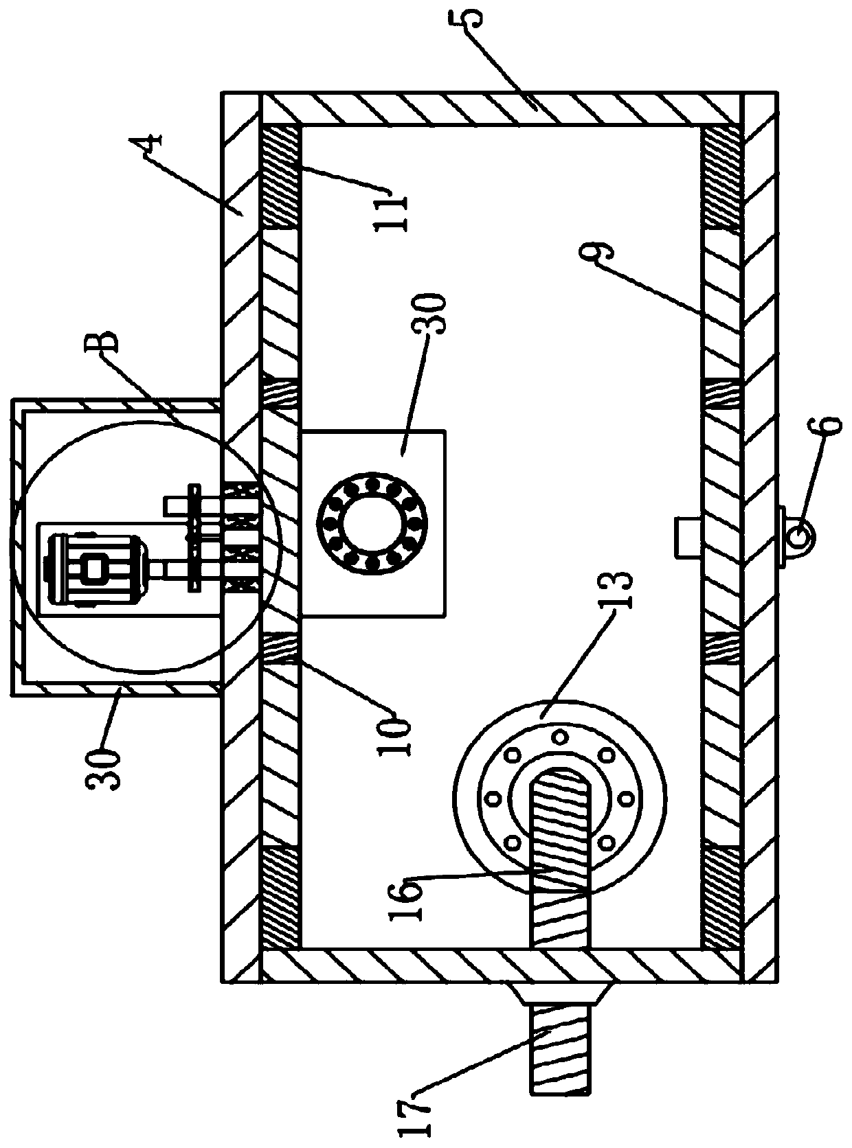
[0034] Example: Please refer to the attached Figure 1-6 , this case is a concrete water storage device with a water level indication function, including a concrete base 1 and a steel channel base 2, the concrete base 1 is used to provide strong support to prevent the main body of the device from sinking downward due to gravity, and the steel channel base 2 Play a stable connection and fixation role. The steel channel base 2 is installed on the upper wall of the concrete base 1. The water storage reinforcement structure is installed on the steel channel base. The water storage reinforcement structure is equipped with water adding auxiliary structures and pressurization water intake structure;

[0035] In the specific implementation process, what needs to be specially explained is that the water storage reinforcement structure in this case mainly includes: a bottom plate 3, a pair of front and rear wall panels 4 with the same structure, a pair of left and right wall panels 5 wi...


PUM


Abstract

The invention discloses a concrete water storage device with a water level indicating function. The concrete water storage device comprises a concrete base and a steel groove base; the steel groove base is installed on the upper wall surface of the concrete base and is provided with a water storage reinforcing structure; and the water storage reinforcing structure is provided with a water adding auxiliary structure and a pressurizing water taking structure. For the concrete water storage device disclosed by the invention, by studying and improving from the aspect of a structure, impact force of water to the device in the water adding process is reduced by adding a silencing tank, and the service life is prolonged; the stability of the device is strengthened by adding transverse tie bars and vertical tie bars, and the device has a function of displaying a water level in real time by adding a communicating pipe, observation of a water storage quantity and use are facilitated; power is provided by adding a servo motor for matching drive of fan blades to run in a staggered manner for pressurized conveying of water, so that the device has the capability of performing water supply on a relatively high construction site; and the structure strength of the device is enhanced, the water quantity is conveniently observed, and high-altitude water supply can be performed.

Description

technical field [0001] The invention relates to the field of water storage devices, in particular to a concrete water storage device with a water level indication function. Background technique [0002] As we all know, a large amount of concrete is needed in the construction process of construction projects. In order to meet the needs of use, many construction sites use on-site mixing to supply concrete. When mixing concrete, a large amount of water is consumed. Under the existing technical conditions, some concrete The mixing work is carried out on a taller building, which makes water supply more difficult. Water supply through manual water supply greatly increases the physical exertion of the staff and seriously affects work efficiency. The existing water storage device structure is too simple , the structural strength is low, a large amount of water storage is easy to cause damage, and it is not convenient to observe the remaining amount of water storage, and the existing...

Claims


Application Information

Patent Timeline
Patent Type & Authority Applications(China)
IPC IPC(8): E04H7/02E04H7/18E03B11/00
CPCE04H7/02E04H7/18E03B11/00
Inventor 梁华国谢舰
Owner 重庆聚钡混凝土有限公司
Why Eureka
Try Eureka