
Motor outer rotor magnetic pole protection layer forming method

A molding method and protective layer technology, applied in the manufacture of the stator/rotor body, etc., can solve the problems of heavy workload, large usage of guide nets and vacuum bags, waste of glue, etc., to reduce workload and shorten glue injection cycle, cost reduction effect

Pending Publication Date: 2020-01-10
XINJIANG GOLDWIND SCI & TECH
View PDF0 Cites 1 Cited by
  • Summary
  • Abstract
  • Description
  • Claims
  • Application Information

AI Technical Summary

Problems solved by technology

[0005] In the existing above-mentioned glue injection process, the use of laying release cloth, guide net and vacuum bag is relatively large, and the workload is correspondingly relatively large, and it is wasteful for the glue to remain on the surface of each component

Method used


Image

  • Motor outer rotor magnetic pole protection layer forming method
  • Motor outer rotor magnetic pole protection layer forming method

Examples


Embodiment Construction

[0028] The core of the present invention is to provide a forming method of the magnetic pole protection layer in the motor rotor assembly, which can reduce the forming workload of the magnetic pole protection layer and greatly reduce the waste of glue.

[0029] In order to enable those skilled in the art to better understand the technical solutions of the present invention, the present invention will be further described in detail below in conjunction with the accompanying drawings and specific embodiments.

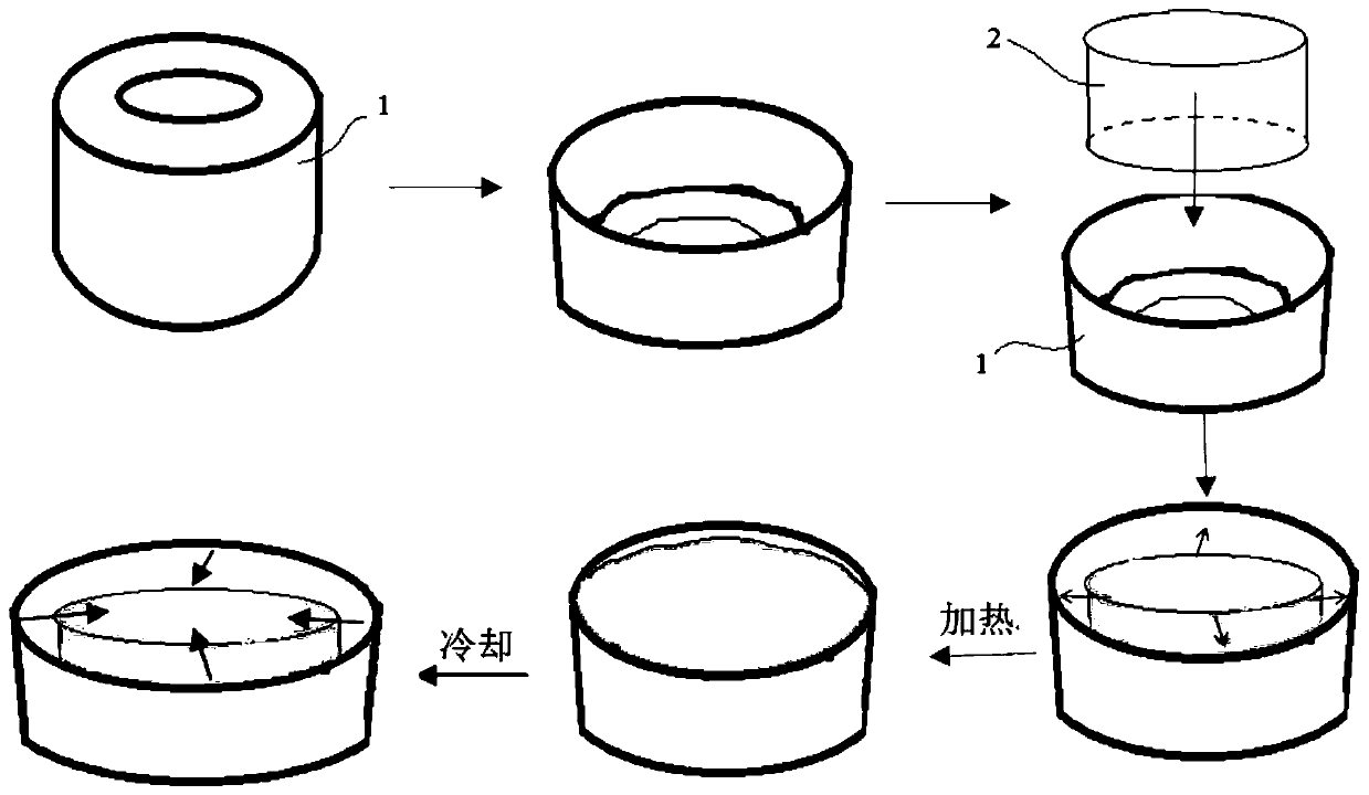
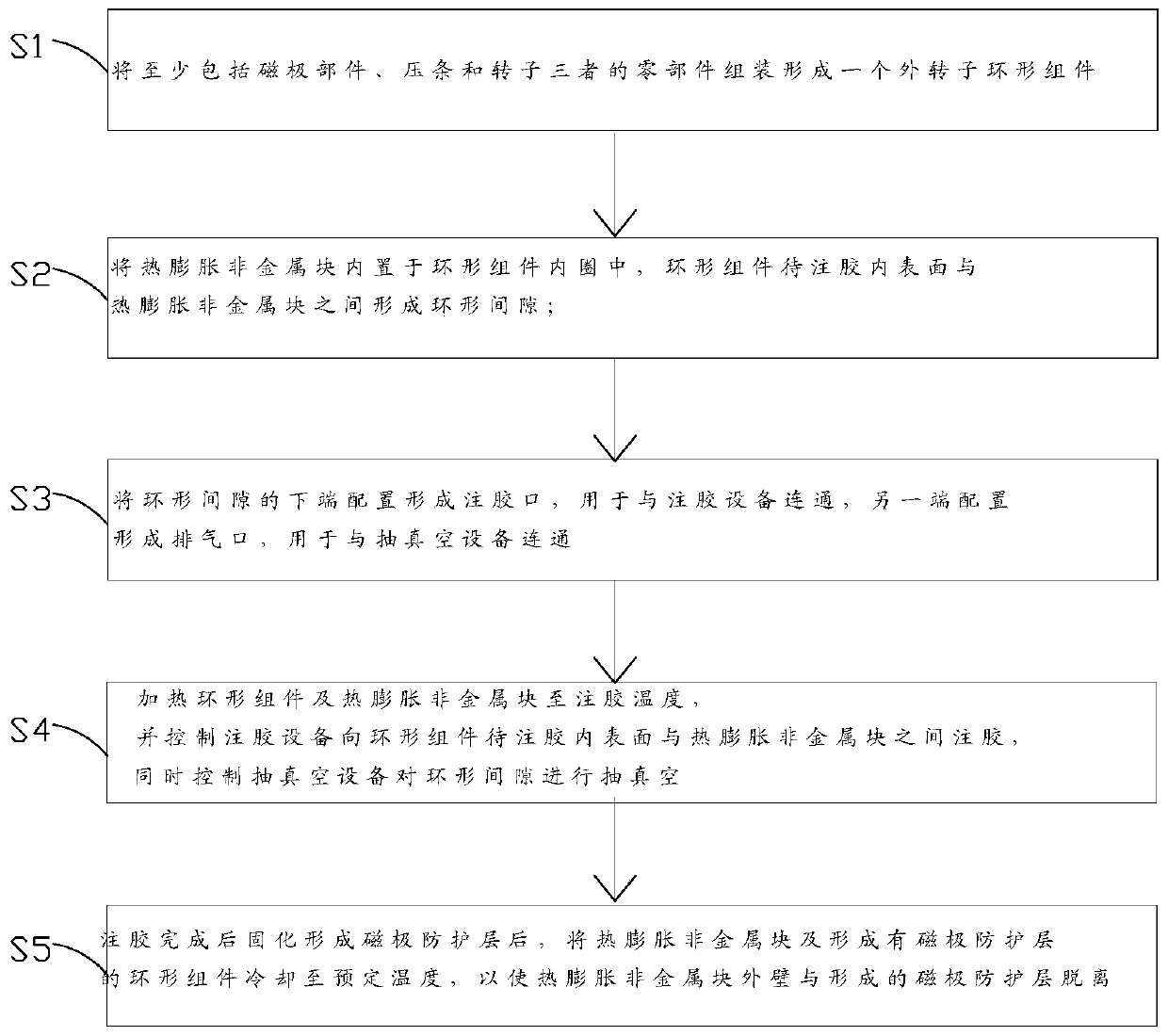
[0030] Please refer to figure 1 with figure 2 , figure 1 It is a schematic flow chart of the forming method of the outer rotor magnetic pole protection layer of the motor in the first embodiment of the present invention; figure 2 It is a flow chart of the forming method of the outer rotor magnetic pole protection layer of the motor provided by the present invention.

[0031] The motor rotor assembly provided by the present invention at least includes components such ...


PUM


Abstract

The invention discloses a motor outer rotor magnetic pole protection layer forming method. In the method, a glue injection requirement and automatic separation of a thermal expansion non-metal block and a magnetic pole protection layer after glue injection are achieved through thermal expansion and cold contraction of the thermal expansion non-metal block, auxiliary glue injection components suchas a vacuum bag film, demolding cloth and a flow guide net do not need to be used, a preparation procedure before glue injection is simplified, a workload is greatly reduced, and a glue injection period can be shortened. And by using the forming method, through controlling pressure between the thermal expansion non-metal block and an internal portion of an annular component, the magnetic pole protection layer is tighter, a solid heat transfer speed is high, the high-quality magnetic pole protection layer can be formed only through one-time glue injection, and a production period is further shortened. Furthermore, the thermal expansion non-metal block is naturally separated from the magnetic pole protection layer after the glue injection is completed, there is almost no residual resin on the surface of the thermal expansion non-metal block, dangerous wastes are greatly reduced, and an environment is protected while cost is reduced.

Description

technical field [0001] The invention relates to the technical field of motor rotor magnetic pole protection, in particular to a forming method of a motor outer rotor magnetic pole protection layer. Background technique [0002] Permanent magnet motor is an electromagnetic device that converts mechanical energy and electrical energy through the medium of magnetic field. It is widely used in various power generation places. Among them, the magnetism of the permanent magnet material of the permanent magnet motor is one of the important factors affecting the power generation performance of the permanent magnet motor. [0003] The permanent magnet motor includes rotor body, bead, magnetic pole parts, etc. The rotor body is generally cylindrical. The pre-processed bead is installed on the inner peripheral wall of the rotor with fasteners such as bolts. Axially push to the corresponding position between the adjacent bead, the cross-section of the bead is generally trapezoidal, tha...

Claims


Application Information

Patent Timeline
Patent Type & Authority Applications(China)
IPC IPC(8): H02K15/02
CPCH02K15/02
Inventor 李术林王栋张世福
Owner XINJIANG GOLDWIND SCI & TECH
Learn More