
Bearing and reducer

A reducer and bearing technology, applied in the field of bearings and reducers, can solve the problem of high failure rate of main bearings

Pending Publication Date: 2020-01-10
SUOTE TRANSMISSION EQUIP
View PDF0 Cites 1 Cited by
  • Summary
  • Abstract
  • Description
  • Claims
  • Application Information

AI Technical Summary

Problems solved by technology

[0005] The purpose of the present invention is to provide a bearing to solve the technical problem of the high failure rate of the main bearing of the reducer in the prior art

Method used


Image

  • Bearing and reducer
  • Bearing and reducer
  • Bearing and reducer

Examples


Embodiment 1

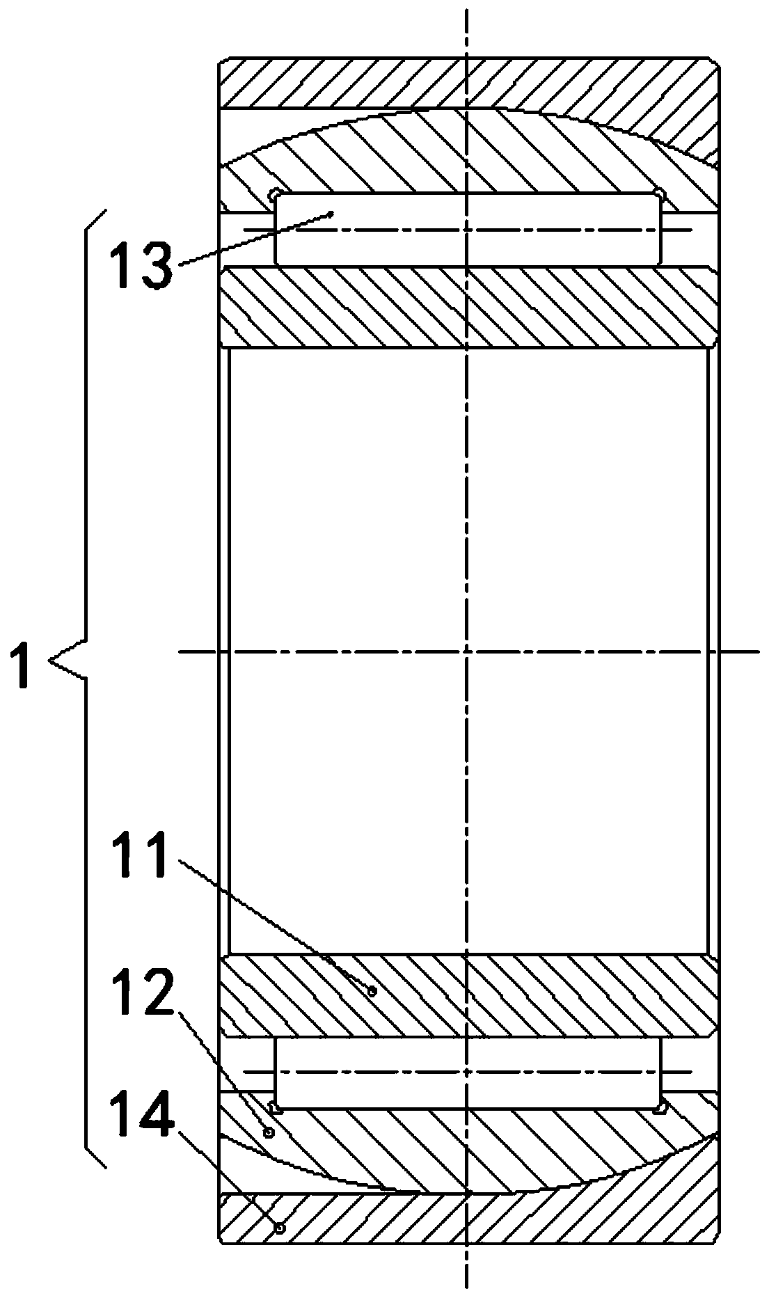
[0031] Bearing 1 provided in this embodiment, such as figure 1 As shown, it includes a bushing 14 and a bearing body; the bearing body includes an inner ring 11, an outer ring 12 and rolling elements; the outer ring 12 is sleeved outside the inner ring 11, and the rolling elements are rotatably installed on the inner ring 11 and the outer ring 12 Between them, the rolling elements are used to bear the radial load; the bushing 14 is sleeved on the outer ring 12, and the outer surface of the outer ring 12 is spherically matched with the inner surface of the bushing 14, so that the axis of the bearing body can be relative to the bushing 14 The axis swings, and the outer ring 12 and the bushing 14 are used to bear the axial load.

[0032] Wherein, the outer ring 12 and the inner ring 11 are arranged coaxially, the outer ring 12 is sleeved on the outside of the inner ring 11, the outer ring 12 and the inner ring 11 are arranged at intervals, and the rolling elements are installed b...

Embodiment 2

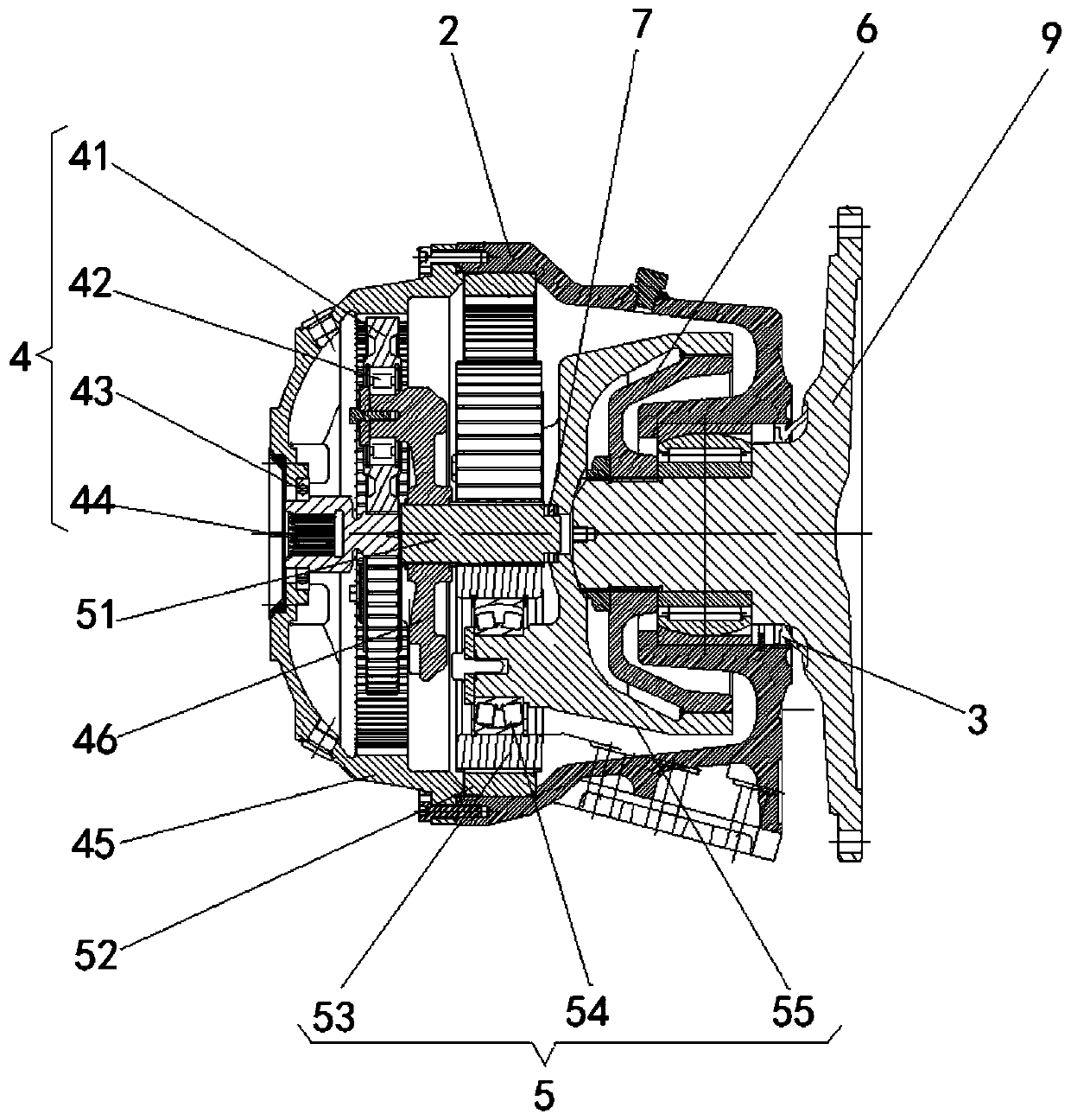
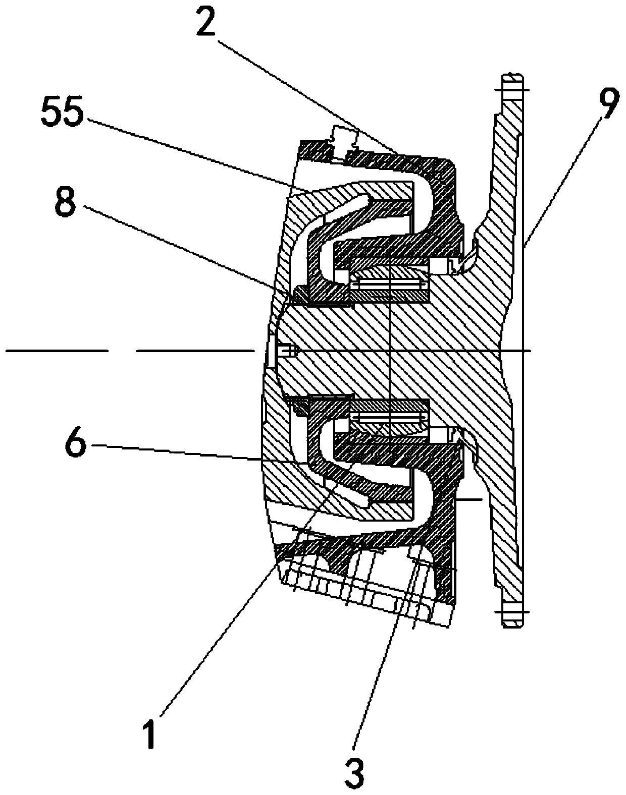
[0045]The reducer provided in this embodiment, such as Figure 1 to Figure 3 As shown, the output member 9 and the bearing 1 provided in Embodiment 1 are included, and the output member 9 is fixedly connected to the inner ring 11 .

[0046] Wherein, the output member 9 may be an output shaft, or any suitable form such as an output flange.

[0047] The output member 9 is fixedly connected with the inner ring 11. When the output member 9 rotates, it drives the inner ring 11 to rotate around the axis of the inner ring 11. The bearing body can support the output member 9, and because the axis of the bearing body can be relatively The axis of the sleeve 14 swings, so that the axis of the output member 9 can be driven to swing relative to the axis of the bush 14 to realize the self-aligning function; since the rolling elements of the bearing 1 bear the radial load, the outer ring 12 and the bush 14 bear the shaft It can separate the axial load and radial load on different parts, th...


PUM


Abstract

The invention provides a bearing and a reducer, and relates to the technical field of transmission devices. The bearing includes a bush and a bearing body, the bearing body includes an inner ring, anouter ring and a rolling body, the outer ring is arranged on the outer side of the inner ring in a sleeving manner, the rolling body is rotatably installed between the inner ring and the outer ring, and the rolling body is used for bearing the radial load; the bush is arranged on the outer ring in a sleeving manner, the outer surface of the outer ring is spherically matched with the inner surfaceof the bush to enable the axis of the bearing body to swing relative to the axis of the bush, and the outer ring and the bush are used for bearing the axial load. Since the rolling body of the bearingbears the radial load, and the outer ring and bush bear the axial load, so that the axial load and radial load are capable of being separated on different parts, the axial load and the radial load are prevented from being concentrated on the same part, the bearing life is prolonged, and the bearing failure rate is reduced.

Description

technical field [0001] The invention relates to the technical field of transmission devices, in particular to a bearing and a reducer. Background technique [0002] In the current engineering construction, in order to reduce the storage amount of building materials on the construction site, it is necessary to place a large amount of building materials away from the construction site. Concrete mixer trucks can realize the mixing operation of building materials during transportation, so concrete mixer trucks are more and more widely used. [0003] The reducer is an important part of the concrete mixer truck. The main bearing of the reducer needs to bear large axial load, radial load and impact load, and the main bearing of the reducer also needs to have the self-aligning function. [0004] In view of the above requirements, the main bearing of the reducer in the prior art uses a self-aligning roller bearing with a large self-aligning angle. However, the axial load and radial ...

Claims


Application Information

Patent Timeline
IPC IPC(8): F16C23/08F16H1/32F16H57/022
CPCF16C23/082F16H1/32F16H57/022
Inventor 肖军宝贾广利赵慧
Owner SUOTE TRANSMISSION EQUIP
Learn More