Sand-out returning fluid stop valve for oil well and application method of stop valve

A shut-off valve and sand washing technology, which is applied in the direction of earthwork drilling, wellbore flushing, wellbore/well components, etc. It can solve the problem that the check valve cannot be installed in the well string, and the installation of the check valve cannot meet the construction requirements and cannot be achieved. environmental protection law and other issues to achieve the effect of solving environmental pollution

Pending Publication Date: 2020-01-10
BC P INC CHINA NAT PETROLEUM CORP +1
View PDF11 Cites 1 Cited by
  • Summary
  • Abstract
  • Description
  • Claims
  • Application Information

AI Technical Summary

Problems solved by technology

[0003] The present invention provides an oil well sand flushing return liquid cut-off valve and its use method. The first purpose is to overcome the problem that in the prior art, during the oil well sand flushing, in the process of replacing a single root, due to the excited pressure of the liquid in the well, some of them also contain When a small amount of gas is connected to a single pipe, the oil pipe coupling is at a height of 10 meters, and the return fluid will be lifted 10 meters high and then sprinkled. The well site is still full of water, which cannot meet the requirements of the "Environmental Protection Law"; the second purpose It is to overcome that in the process of reverse circulation sand washing in the prior art, the flow direction of the pumped liquid is consistent with the flow direction of the return liquid when the sand washing is replaced with a single one. The project is complex and needs to be flushed and recoiled, and the installation of check valves cannot meet the construction requirements

Method used


Image

  • Sand-out returning fluid stop valve for oil well and application method of stop valve

Examples


Embodiment 1

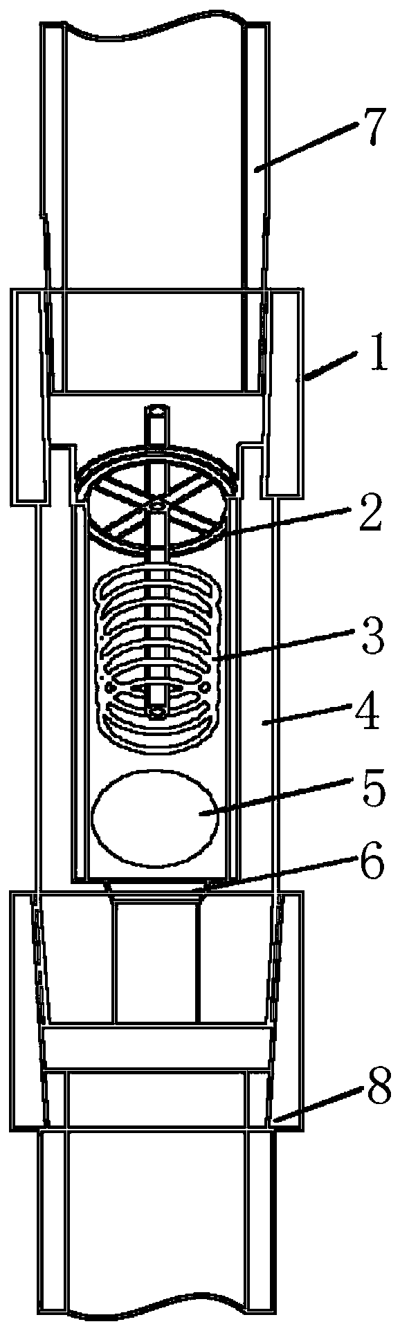
[0022] A cut-off valve for oil well sand flushing and return fluid, comprising an upper joint 1, a baffle plate 2, a pressure balance spring 3, a stop valve body 4, a setting ball 5, a ball seat 6, an upper oil pipe pin 7 and a lower oil pipe box 8 , the upper oil pipe pin 7, the upper joint 1, the stop valve body 4 and the lower oil pipe box 8 are connected sequentially from top to bottom, and the inside of the stop valve body 4 is provided with a baffle plate 2, a pressure balance spring 3, The setting ball 5 and the ball seat 6 are connected to the pressure balance spring 3 under the baffle plate 2 and both the baffle plate 2 and the pressure balance spring 3 are located on the upper part of the stop valve body 4, and the ball seat 6 is connected to the lower part of the stop valve body 4 for setting. The ball 5 can be set on the ball seat 6 .

Embodiment 2

[0024] Such as figure 1 As shown, a cut-off valve for oil well sand flushing return fluid includes an upper joint 1, a baffle plate 2, a pressure balance spring 3, a stop valve body 4, a setting ball 5, a ball seat 6, an upper oil pipe pin 7 and a lower oil pipe The female buckle 8, the upper oil pipe male buckle 7, the upper joint 1, the shut-off valve body 4 and the lower oil pipe buckle 8 are connected sequentially from top to bottom, and the inside of the shut-off valve body 4 is provided with a baffle 2 and a pressure balance from top to bottom. Spring 3, setting ball 5 and ball seat 6, the baffle plate 2 is connected to the pressure balance spring 3 and the baffle plate 2 and pressure balance spring 3 are located on the upper part of the stop valve body 4, and the ball seat 6 is connected to the lower part of the stop valve body 4 , The setting ball 5 can be set on the ball seat 6. This oil well sand flushing return fluid cut-off valve is designed by using the principle...

Embodiment 3

[0034] On the basis of embodiment 2, the use method of the oil well sand flushing return liquid shut-off valve is as follows:

[0035]During the process of pumping in liquid for circulating sand flushing, the liquid flow pushes the setting ball 5 away from the ball seat 6, and the shut-off valve of the oil well sand flushing return liquid is in an open state, and the sand flushing operation can be carried out;

[0036] When changing a single piece, stop pumping liquid, the setting ball 5 falls on the ball seat 6 under the action of its own weight and the elastic force of the pressure balance spring 3, the shut-off valve of the oil well sand flushing return fluid is closed, and the wellhead stops returning water ;

[0037] When it is necessary to establish a positive circulation channel, the setting ball 5 can be crushed by lame pressure, and the shut-off valve of the oil well sand flushing and return fluid can be opened to carry out positive and negative circulation.

[0038]...


PUM


Abstract

The invention belongs to the technical field of tools for the oil and gas field and particularly provides a sand-out returning fluid stop valve for an oil well and an application method of the stop valve. The stop valve comprises an upper connector, a baffle, a pressure balance spring, a stop valve body, a setting ball, a ball seat, an upper oil pipe male buckle and a lower oil pipe female buckle.The problems are solved that in the prior art, during sand-out of the oil well, in the process of replacing a joint, there is still full of water in the well field, the requirement of the environmental protection act cannot be met, in the reverse-circulation sand-out process, the flow direction of pumped fluid is identical to that of returning fluid during sand-out and joint replacement, a checkvalve cannot be installed on an in-well pipe column, if the project is complex in the sand-out process, forward sand-out and reverse sand-out are needed, and installation of the check valve cannot meet the construction demand. According to the stop valve, overflowing of the returning fluid in the sand-out operation joint replacement process can be effectively blocked, the environmental pollution is avoided, site construction is effectively guided, the sand-out operation efficiency of a common oil pipe is improved, and the safety and environment protection risks are reduced.

Description

technical field [0001] The invention belongs to the technical field of oil and gas field tools, and in particular relates to an oil well sand flushing return liquid shut-off valve and a use method thereof. Background technique [0002] At present, the sand flushing of oil wells is basically reverse circulation and open operation. After the return fluid is collected at the wellhead, it directly enters the sewage pit through the drainage channel, and is sprinkled on the well site. With the promulgation of the new "Environmental Protection Law", this sand washing mode is no longer suitable for the job site, and open operation is not advisable. In the absence of new technology to replace it, the site can only connect high-pressure elbows to a single oil pipe. And the high-pressure water hose, which connects a large amount of return liquid to the grit chamber for recovery. However, in the process of replacing a single pipe, due to the exciting pressure of the liquid in the well,...

Claims


Application Information

Patent Timeline
Patent Type & Authority Applications(China)
IPC IPC(8): E21B21/10
CPCE21B21/10
Inventor 王金刚王鸿章田玉琛包福忠祁俊武苏峰方军伟张延平殷学明袁海平安鹏飞王伟宋超宋凤军张林何拥军
Owner BC P INC CHINA NAT PETROLEUM CORP
Why Eureka
Try Eureka