
Bolting device between prefabricated decks of prefabricated bridges

A technology for prefabricated and prefabricated bridges, applied in the field of bridge construction, can solve problems such as affecting the work process, difficult positioning of prefabricated bridge panels, and troublesome processes, and achieve the effect of improving the progress of the project.

Active Publication Date: 2021-11-12
江苏月生达机械制造有限公司
View PDF13 Cites 0 Cited by
  • Summary
  • Abstract
  • Description
  • Claims
  • Application Information

AI Technical Summary

Problems solved by technology

[0002] During the assembly and installation of prefabricated bridge panels, the connection between two prefabricated bridge panels is usually connected by cast-in-place reinforced concrete. The steel bars reserved for the two prefabricated bridge panels are welded and fixed, and finally concrete is poured. The process of reinforcing steel bars is relatively troublesome; and when two prefabricated bridge panels are connected, it is relatively difficult to locate the prefabricated bridge panels, which affects the work process. In the prior art, the technical scheme of pre-binding steel bars and then welding is adopted, such as patent document CN109778688A , needs to be operated one by one on site, and there is the disadvantage that the U-shaped steel bars at the ends of the prefabricated slabs on both sides are easily misaligned with each other. In addition, although CN208009273U and CN204209817U have adopted a snap-fit ​​fixing structure designed to surround the built-in card slots on the outside of the vertical steel bars, However, this type of engaging structure can only be used for the outside of the vertical reinforcement, but cannot be fixedly engaged for the transverse U-shaped reinforcement that needs to be arranged in a staggered manner.

Method used


Image

  • Bolting device between prefabricated decks of prefabricated bridges
  • Bolting device between prefabricated decks of prefabricated bridges
  • Bolting device between prefabricated decks of prefabricated bridges

Examples


Embodiment Construction

[0025] The following will clearly and completely describe the technical solutions in the embodiments of the present invention with reference to the accompanying drawings in the embodiments of the present invention. Obviously, the described embodiments are only some, not all, embodiments of the present invention. Based on the embodiments of the present invention, all other embodiments obtained by persons of ordinary skill in the art without making creative efforts belong to the protection scope of the present invention.

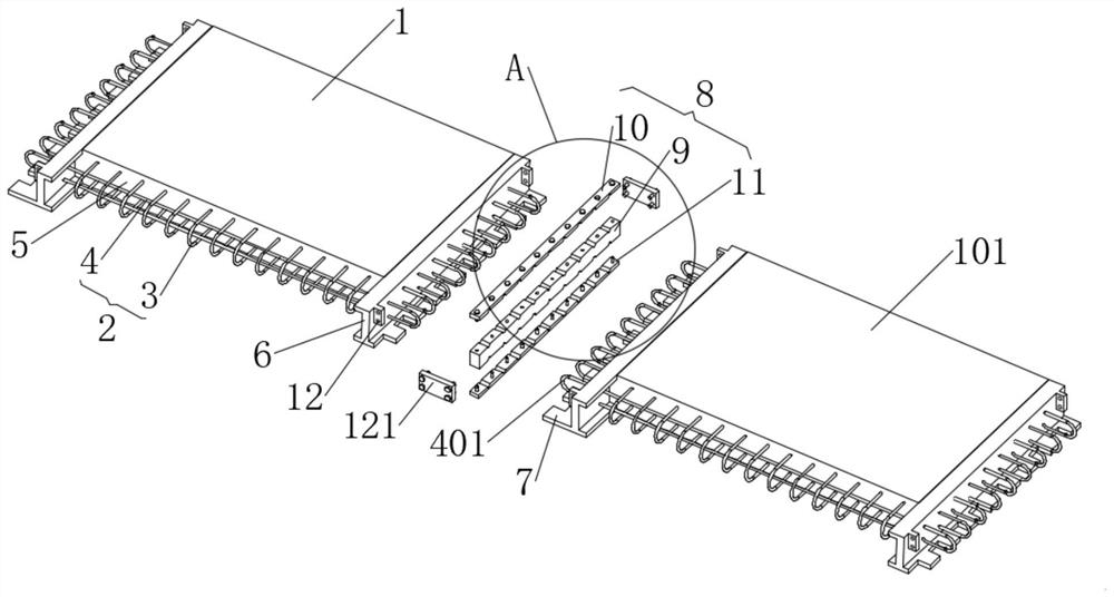
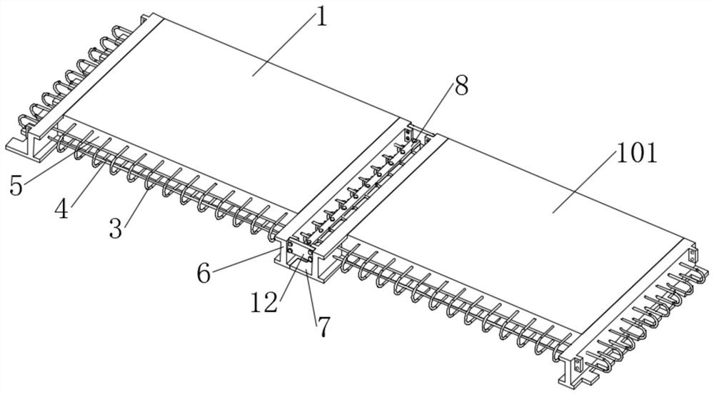
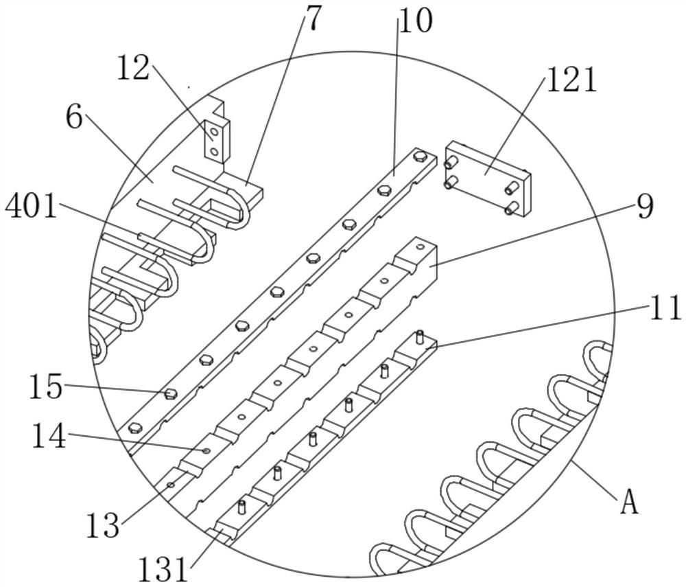
[0026] The present invention provides such Figure 1-7 The shown bolting device between the prefabricated bridge decks of the prefabricated bridge includes a first bridge deck 1, a second bridge deck 101 and a connecting member 8, and the first bridge deck 1 and the second bridge deck 101 are made of a steel skeleton 2 And the panel concrete layer 5 wrapped and poured on the outside of the steel skeleton 2 is formed. Both ends of the first bridge panel 1 and t...


PUM


Abstract

The invention discloses a bolting device between prefabricated bridge decks of an assembled bridge, relates to the field of bridge construction, and comprises a first bridge deck, a second bridge deck and connecting members, and both ends of the first bridge deck and the second bridge deck are arranged There are steel plates, the ends of the transverse steel bars inside the first bridge deck and the second bridge deck pass through the steel plates and are bent into reserved steel bars, which are interspersed along the middle of the reserved steel bars set at the ends of the first bridge deck and the second bridge deck There are connecting components. In the present invention, the positioning column passes through the middle part of the reserved steel bar, so that the reserved steel bar is clamped in the slot opened by the positioning column, and the reserved steel bar is sandwiched by the upper splint and the lower splint to prevent the reserved steel bar from detaching, and finally The concrete filling layer is poured at the junction of the first bridge deck and the second bridge deck, and the connecting members and the reserved steel bars are connected and fixed without welding, which effectively improves the progress of the project.

Description

technical field [0001] The invention relates to the field of bridge construction, in particular to a bolting device between prefabricated bridge decks of an assembled bridge. Background technique [0002] During the assembly and installation of prefabricated bridge panels, the connection between two prefabricated bridge panels is usually connected by cast-in-place reinforced concrete. The steel bars reserved for the two prefabricated bridge panels are welded and fixed, and finally concrete is poured. The process of reinforcing steel bars is relatively troublesome; and when two prefabricated bridge panels are connected, it is relatively difficult to locate the prefabricated bridge panels, which affects the work process. In the prior art, the technical scheme of pre-binding steel bars and then welding is adopted, such as patent document CN109778688A , needs to be operated one by one on site, and there is the disadvantage that the U-shaped steel bars at the ends of the prefabri...

Claims


Application Information

Patent Timeline
Patent Type & Authority Patents(China)
IPC IPC(8): E01D19/12E01D21/00
CPCE01D19/125E01D21/00
Inventor 张鹏王磊姚亮李怀奇李靖贺辉刘太锁尚俊胡鹏涛曹炳强赵文广张丽娜魏志峰
Owner 江苏月生达机械制造有限公司
Learn More