
Full-automatic cutting equipment for stainless steel pipes

A technology for cutting equipment and stainless steel pipes, which is applied in the field of automatic cutting equipment for stainless steel pipes, which can solve the problem of uneven cutting edges, achieve the effect of flat blades and prevent position deviation

Active Publication Date: 2020-03-24
湖南旺坤管业有限公司
View PDF7 Cites 0 Cited by
  • Summary
  • Abstract
  • Description
  • Claims
  • Application Information

AI Technical Summary

Problems solved by technology

[0003] Since the outer surface of the stainless steel tube is cylindrical, when the stainless steel tube is clamped, it is usually a line contact, and only the axial line contact is realized, and only the longitudinal position is limited. When cutting, due to the extrusion of the blade Cutting, while causing the stainless steel tube to rotate, will cause the stainless steel tube to shift to both sides, resulting in uneven cutting edge

Method used


Image

  • Full-automatic cutting equipment for stainless steel pipes
  • Full-automatic cutting equipment for stainless steel pipes
  • Full-automatic cutting equipment for stainless steel pipes

Examples


specific Embodiment

[0029] see Figure 1-Figure 12 , the specific embodiments of the present invention are as follows:

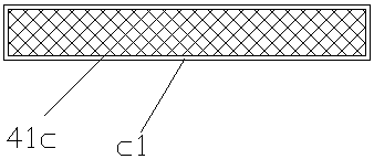
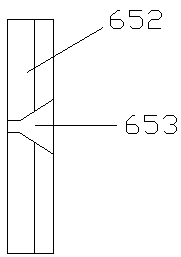
[0030] Its structure includes a frame 1, a cylinder 2, a workbench 3, a motor 4, a cutting blade 5, and a clamping structure 6. The cylinder 2 is installed on the inside of the frame 1 and is mechanically connected, and the workbench 3 is installed horizontally on the machine. The upper end of the frame 1 is welded, the motor 4 is hinged to the upper end of the cylinder 2 and located above the workbench 3, the motor 4 is connected to the cutting blade 5 through a chain, and the clamping structure 6 is horizontally installed on the workbench 3 above and below the cutting blade 5; the clamping structure 6 includes a telescopic cylinder 61, a limiting plate 62, a chassis 63, a movable structure 64, a fixed structure 65, and a guide rod 66, and the limiting plate 62 is welded vertically on On the upper end of the chassis 63, the telescopic cylinder 61 is installed on the left side...


PUM


Abstract

The invention discloses full-automatic cutting equipment for stainless steel pipes. The full-automatic cutting equipment structurally comprises a rack, an air cylinder, a workbench, a motor, a cuttingblade and a clamping structure. The air cylinder is mounted on the inner side of the rack, the workbench is horizontally mounted at the upper end of the rack, the motor is connected to the upper endof the air cylinder in a hinged manner, the motor and the cutting blade are connected through a chain, and the clamping structure is horizontally mounted above the workbench. The clamping structure comprises a telescopic air cylinder, a limiting plate, a bottom frame, a movable structure, a fixed structure and guide rods. The limiting plate is vertically welded to the upper end of the bottom frame, the telescopic air cylinder is mounted on the left side of the limiting plate, the movable structure is mounted at the right end of the telescopic air cylinder and abuts against the inner side of the bottom frame, the fixed structure is welded to the upper end of the bottom frame, and the guide rods penetrate through the limiting plate to be connected with the movable structure. The movable structure is arranged on the left side of the fixed structure, contact limiting of multiple positions is formed, position shifting caused by rotation of the stainless steel pipes during cutting is avoided, and cutting knife edges are smoother.

Description

technical field [0001] The invention belongs to the field of pipe cutting, and in particular relates to a fully automatic cutting equipment for stainless steel pipes. Background technique [0002] Stainless steel pipe is a kind of hollow long round steel. At present, the stainless steel pipes manufactured are all extended in the axial direction. They are intercepted and cut according to the needs of use. Due to the high bending and tensile strength of stainless steel pipes, Therefore, it is necessary to use automatic cutting equipment for stainless steel pipes to cut stainless steel pipes to meet the processing requirements in the later stage, but the existing technology has the following deficiencies: [0003] Since the outer surface of the stainless steel tube is cylindrical, when the stainless steel tube is clamped, it is usually a line contact, and only the axial line contact is achieved, and only the longitudinal position is limited. When cutting, due to the extrusion o...

Claims


Application Information

Patent Timeline
Patent Type & Authority Applications(China)
IPC IPC(8): B23D21/00B23Q3/08
CPCB23D21/00B23Q3/064B23Q3/08B23Q2703/04
Inventor 周锦波
Owner 湖南旺坤管业有限公司
Learn More