
Steel bar bending forming machining device

A steel bar bending and forming processing technology, applied in the field of steel bar bending, can solve the problems that small electric steel bar bending machines are not suitable for power supply, cannot accurately control the bending radian and angle of steel bars, and it is not suitable to use large electric mechanical bending machines. Speed ​​up on-site construction operations, improve on-site construction quality and progress, and prevent the handle from slipping

Pending Publication Date: 2020-01-10
CHINA NO 15 METALLURGICAL CONSTR GRP
View PDF0 Cites 0 Cited by
  • Summary
  • Abstract
  • Description
  • Claims
  • Application Information

AI Technical Summary

Problems solved by technology

[0003] The main purpose of the present invention is to propose a steel bar bending and forming processing device, which aims to solve the problem that the existing construction site is not suitable for using large electric mechanical bending machines, small electric steel bending machines are not suitable for power supply and other conditions, and the existing small manual bending machines There is a deviation between the bending size and the actual size on site, and the bending radian and angle of the steel bar cannot be precisely controlled

Method used


Image

  • Steel bar bending forming machining device
  • Steel bar bending forming machining device
  • Steel bar bending forming machining device

Examples


Embodiment Construction

[0029] It should be noted that if there are directional indications (such as up, down, left, right, front, back...) in the embodiment of the present invention, the directional indications are only used to explain how to move in a certain posture (as shown in the accompanying drawings). If the specific posture changes, the directional indication will also change accordingly.

[0030] In addition, if there are descriptions involving "first", "second" and so on in the embodiments of the present invention, the descriptions of "first", "second" and so on are only for descriptive purposes, and should not be interpreted as indicating or implying Its relative importance or implicitly indicates the number of technical features indicated.

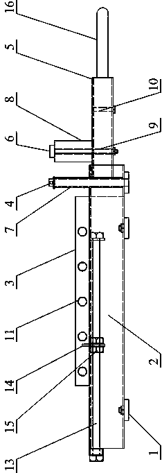
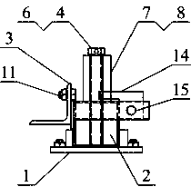
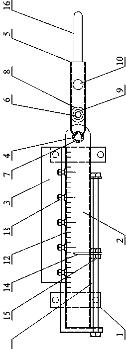
[0031] The invention proposes a steel bar bending and forming processing device, Figure 1 to Figure 5 It is a schematic diagram of an embodiment of the steel bar bending forming processing device proposed by the present invention.

[0032] see F...


PUM


Abstract

The invention discloses a steel bar bending forming machining device. The steel bar bending forming machining device comprises a strip-shaped operation table which is fixed at a base, a positioning plate which is arranged on the strip-shaped operation table and is positioned on the rear side surface of the strip-shaped operation table in the width direction, a positioning shaft which is arranged on the strip-shaped operation table and is positioned at one end of the strip-shaped operation table in the length direction, as well as a rotating rod hinged to the positioning shaft, wherein the rotating rod is provided with a profiling shaft which is arranged at intervals with the positioning shaft, the positioning shaft is sleeved with a positioning shaft sleeve, the profiling shaft is sleevedwith a profiling shaft sleeve, and both the positioning shaft sleeve and the profiling shaft sleeve can rotate along with bending of the steel bar. In the technical scheme provided by the steel bar bending forming machining device, the rotating rod can rotate counterclockwise so as to form a containing channel between the positioning shaft sleeve and the positioning plate, the rotating rod can rotate clockwise so that a guide channel is formed between the positioning shaft sleeve and the profiling shaft sleeve, then the steel bar placed in the containing channel can be adjusted and fixed, thesteel bar is subjected to bending machining through guiding of the guide channel, and therefore the bending radian and the angle of the steel bar are conveniently and accurately controlled.

Description

technical field [0001] The invention relates to the technical field of steel bar bending in construction engineering, in particular to a steel bar bending forming processing device. Background technique [0002] At present, on the construction site of construction projects, the commonly used steel bending tools mainly include manual bending machines and electric mechanical bending machines. For projects with small quantities, it is not suitable to purchase from the perspective of cost and portability. Even if there is a small electric steel bending machine, it is not suitable for places where the construction site is limited by power supply and other conditions; the second is the small manual bending machine purchased in the current market. It only plays the role of steel bar bending, and there is a deviation between the bending size and the actual size on site, and the bending arc and angle of the steel bar cannot be accurately controlled. Therefore, the control of the bend...

Claims


Application Information

Patent Timeline
IPC IPC(8): B21F1/00B21C51/00
CPCB21F1/002B21C51/00
Inventor 崔国柱
Owner CHINA NO 15 METALLURGICAL CONSTR GRP
Learn More