
Parallel-type three-degree-of-freedom piezoelectric resonance self-actuating mechanism and excitation method thereof

An actuating mechanism, piezoelectric resonance technology, applied in the direction of piezoelectric effect/electrostrictive or magnetostrictive motors, generators/motors, electrical components, etc., can solve the problems of slow speed and small driving force

Active Publication Date: 2020-01-07
CHONGQING UNIV OF POSTS & TELECOMM
View PDF8 Cites 2 Cited by
  • Summary
  • Abstract
  • Description
  • Claims
  • Application Information

AI Technical Summary

Problems solved by technology

The advantage of the non-resonant excitation method is that it has nanometer-level high precision, but the disadvantage is that the driving force is small and the speed is slow

Method used


Image

  • Parallel-type three-degree-of-freedom piezoelectric resonance self-actuating mechanism and excitation method thereof
  • Parallel-type three-degree-of-freedom piezoelectric resonance self-actuating mechanism and excitation method thereof
  • Parallel-type three-degree-of-freedom piezoelectric resonance self-actuating mechanism and excitation method thereof

Examples


specific Embodiment approach 1

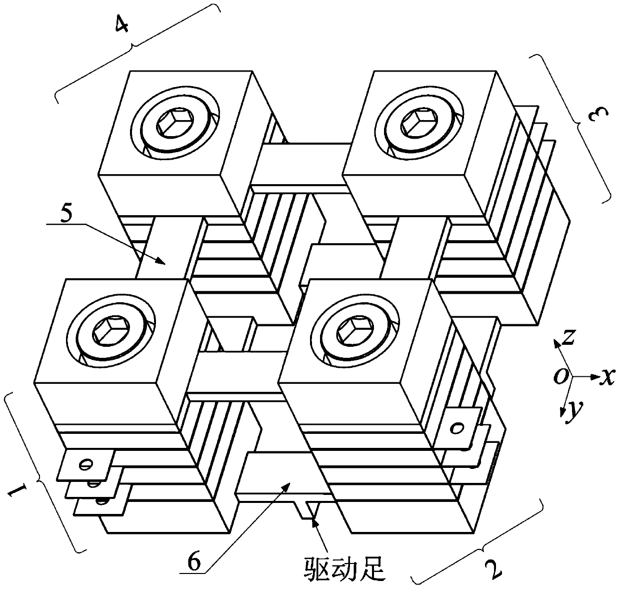
[0015] Specific implementation mode 1. Combination Figure 1-Figure 3 To illustrate this specific embodiment, the parallel three-degree-of-freedom piezoelectric resonant self-actuating mechanism described in this embodiment includes four columnar piezoelectric transducers 1, 2, 3 and 4 with identical structures and four shared Connecting beam 5, four driving beams 6,

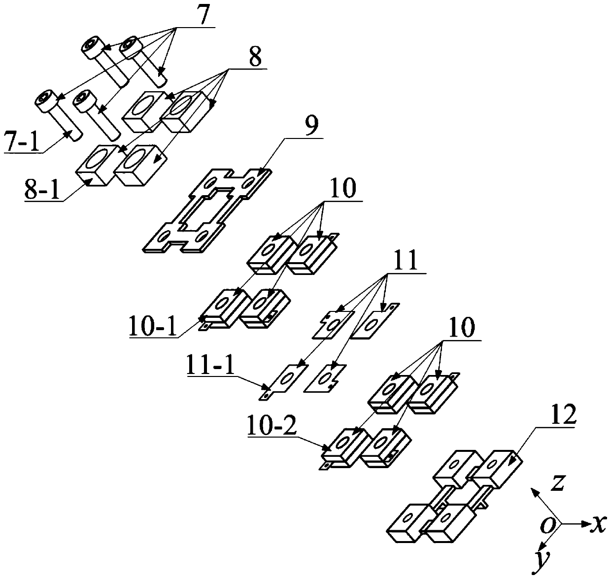
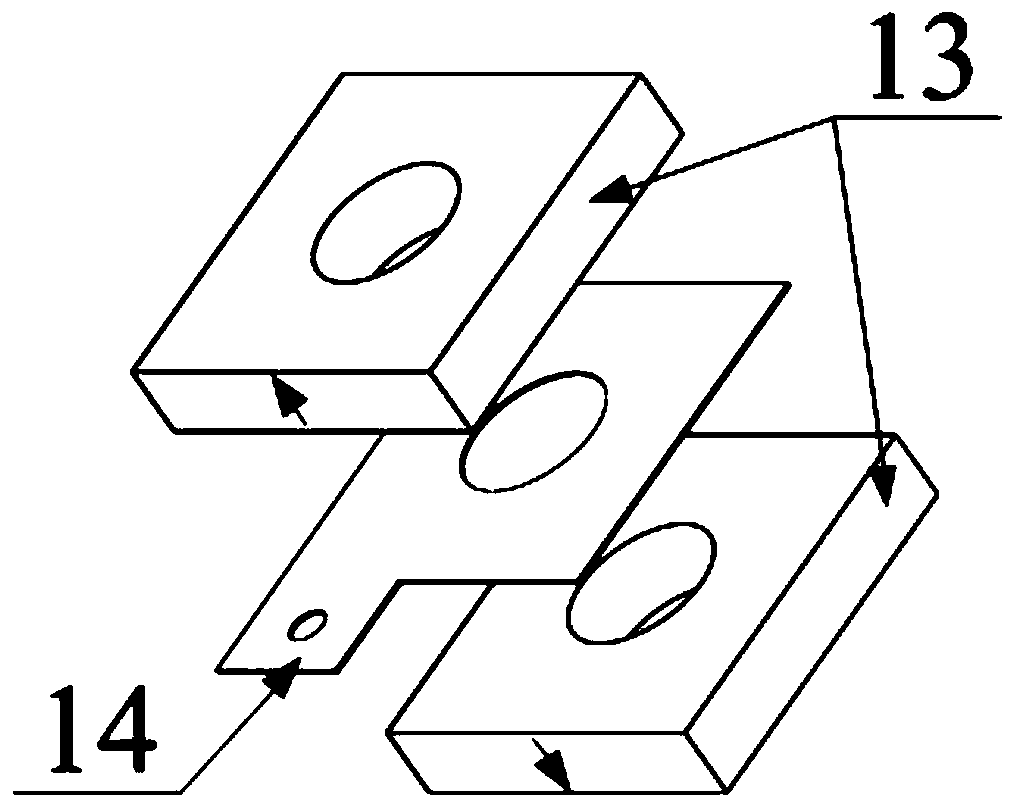
[0016] The structures of the columnar piezoelectric transducers 1, 2, 3 and 4 are the same, and the columnar piezoelectric transducer 1 is taken as an example for illustration. The components included in the columnar piezoelectric transducer 1 include a Screw 7-1, a terminal column 8-1, a connecting plate 9, two piezoelectric ceramic components 10-1, 10-2, a ground electrode piece 11 and a driving terminal column 12, wherein the connecting plate 9 and the driving terminal column 12 are common parts for four columnar piezoelectric transducers. refer to figure 1 , the four connecting beams 5 are actually the pa...

specific Embodiment approach 2

[0020] Specific Embodiment 2. The difference between this embodiment and the parallel-connected three-degree-of-freedom piezoelectric resonant self-actuating mechanism described in Specific Embodiment 1 is that four phases with a phase difference of π / 2 are provided for the columnar voltage conversion electric energy device. Periodic sinusoidal voltage signal V a , V b , V c , V d , the four-phase voltage signals can be V a =V m sin(ωt), V b =V m sin(ωt+π / 2), V c =V m sin(ωt+π), V d =V m sin(ωt+3π / 2), where V m Indicates the amplitude of the voltage signal, and the frequency ω of the voltage signal is close to or consistent with the first-order longitudinal vibration natural frequency of the cylindrical piezoelectric transducer to be excited.

[0021] In this embodiment, setting the working plane: first set the Cartesian rectangular coordinate system, the three axes are x, y, z respectively, o is the origin of the coordinate system, the xoy plane is selected as the ...

specific Embodiment approach 3

[0025] Embodiment 3. The difference between this embodiment and the parallel three-degree-of-freedom piezoelectric resonant self-actuating mechanism described in Embodiment 1 is that each piezoelectric ceramic sheet is composed of a piezoelectric body and a pair of electrode coatings , the two coatings that make up the pair of electrode coatings are respectively located on the square surfaces on both sides of the piezoelectric body.

[0026] The piezoelectric body described in this embodiment is formed of lead zirconate titanate piezoelectric ceramics, but is not limited to lead zirconate titanate piezoelectric ceramics, and can also be formed of other piezoelectric materials such as polyvinylidene fluoride and aluminum nitride. Piezoelectric body. The electrode coating is realized by coating of appropriate metal materials such as Al, Cu, Ag, Ag-Pd alloy and the like arranged on the surface of the piezoelectric ceramic sheet.

[0027] Specific embodiment four, combine figure...


PUM


Abstract

The invention relates to a parallel-type three-degree-of-freedom piezoelectric resonance self-actuating mechanism and an excitation method thereof and belongs to the field of piezoelectric driving. The parallel-type three-degree-of-freedom piezoelectric resonance self-actuating mechanism and the excitation method thereof can be applied to the fields of precision driving, medical treatment, micromachinery and the like. The invention aims to solve the problem that an existing three-degree-of-freedom piezoelectric self-actuating device is small in output force, high in cost and insufficient in actuating capacity. The three-degree-of-freedom piezoelectric resonance self-actuating mechanism of the invention is of a transducer parallel structure; the electric resonance self-actuating mechanism comprises four columnar piezoelectric transducers of the same structure and connecting devices of the columnar piezoelectric transducers; and the self-actuating mechanism comprises four driving feet used for combined actuation. According to the excitation method of the self-actuating mechanism, the sequential longitudinal vibration of the four columnar piezoelectric transducers is respectively excited through two-phase or four-phase voltage excitation signals according to a translation or rotation motion mode, so that the combined longitudinal vibration of the four columnar piezoelectric transducers is formed to drive the driving feet to move, and therefore, the three-degree-of-freedom actuating function of the self-actuating mechanism on a working plane is realized.

Description

technical field [0001] The present invention relates to a parallel-connected three-degree-of-freedom piezoelectric resonant self-actuating mechanism and its excitation method. Actuating mechanism, and by adopting the excitation method, the piezoelectric resonant self-actuating mechanism can realize its three-degree-of-freedom actuating function on the plane, and the invention belongs to the field of piezoelectric driving technology. Background technique [0002] The piezoelectric self-actuating mechanism converts electrical energy into the vibration energy of the vibrating body by using the inverse piezoelectric effect of the piezoelectric material, and converts the vibration energy into the kinetic energy of the self-actuating mechanism body through the contact friction between the driving foot and the working surface. Achieve linear or rotary motion from a self-actuating mechanism. [0003] The remarkable advantages of the piezoelectric self-actuating mechanism are: easy ...

Claims


Application Information

Patent Timeline
IPC IPC(8): H02N2/00
CPCH02N2/0095H02N2/0075H02N2/008H02N2/005
Inventor 周详宇余桑魏博汪从哲杨德伟
Owner CHONGQING UNIV OF POSTS & TELECOMM
Learn More