A parallel three-degree-of-freedom piezoelectric resonance self-actuating mechanism and its excitation method
An actuation mechanism and piezoelectric resonance technology, which is applied to piezoelectric effect/electrostrictive or magnetostrictive motors, generators/motors, electrical components, etc., can solve problems such as slow speed and small driving force
- Summary
- Abstract
- Description
- Claims
- Application Information
AI Technical Summary
Problems solved by technology
Method used
Image


Examples
specific Embodiment approach 1
[0015] Specific implementation mode 1. Combination Figure 1-Figure 3 Illustrating this specific embodiment, the parallel three-degree-of-freedom piezoelectric resonance self-actuating mechanism described in this embodiment includes four cylindrical piezoelectric transducers 1 , 2 , 3 and 4 with identical structures and four common ones. Connecting beam 5, four driving beams 6,
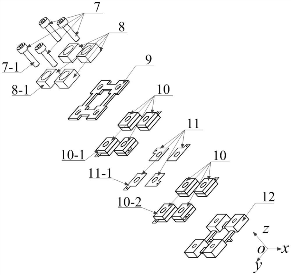
[0016] The structures of the cylindrical piezoelectric transducers 1, 2, 3 and 4 are all the same. The cylindrical piezoelectric transducer 1 is used as an example for illustration. The components included in the cylindrical piezoelectric transducer 1 include a Screw 7-1, an end post 8-1, a connection plate 9, two piezoelectric ceramic components 10-1, 10-2, a ground electrode piece 11 and a driving end post 12, wherein the connection plate 9 and the driving end post 12 are the common parts of the four cylindrical piezoelectric transducers. refer to figure 1 , the four connecting beams 5 are actual...
specific Embodiment approach 2
[0020] Specific embodiment 2. The difference between this embodiment and the parallel three-degree-of-freedom piezoelectric resonance self-actuating mechanism described in specific embodiment 1 is that it provides a four-phase phase difference with a phase difference of π / 2 for the columnar piezoelectric transducer. Periodic sinusoidal voltage signal V a , V b , V c , V d , the four-phase voltage signal can be V a =V m sin(ωt), V b =V m sin(ωt+π / 2), V c =V m sin(ωt+π), V d =V m sin(ωt+3π / 2), where V m It represents the amplitude of the voltage signal, and the frequency ω of the voltage signal is close to or consistent with the natural frequency of the first-order longitudinal vibration of the cylindrical piezoelectric transducer to be excited.
[0021] In this embodiment, set the working plane: first set the Cartesian Cartesian coordinate system, the three axes are x, y, z respectively, o is the origin of the coordinate system, the xoy plane is selected as the horiz...
specific Embodiment approach 3
[0025] Embodiment 3. The difference between this embodiment and the parallel three-degree-of-freedom piezoelectric resonance self-actuating mechanism described in Embodiment 1 is that each piezoelectric ceramic sheet is composed of a piezoelectric body and a pair of electrode coatings , the two coatings that make up this pair of electrode coatings are located on the two-sided square surfaces of the piezoelectric body, respectively.
[0026] The piezoelectric body described in this embodiment is formed of lead zirconate titanate piezoelectric ceramics, but is not limited to lead zirconate titanate piezoelectric ceramics, and may also be formed of other piezoelectric materials such as polyvinylidene fluoride and aluminum nitride. Piezoelectric. The electrode coating is realized by suitable metal material coating such as Al, Cu, Ag, Ag-Pd alloy, etc. arranged on the surface of the piezoelectric ceramic sheet.
[0027] Specific embodiment four, combination figure 1 Describing th...
PUM
 Abstract
Description
Claims
Application Information
 - R&D
- Intellectual Property
- Life Sciences
- Materials
- Tech Scout
- Unparalleled Data Quality
- Higher Quality Content
- 60% Fewer Hallucinations
Browse by: Latest US Patents, China's latest patents, Technical Efficacy Thesaurus, Application Domain, Technology Topic, Popular Technical Reports.
© 2025 PatSnap. All rights reserved.Legal|Privacy policy|Modern Slavery Act Transparency Statement|Sitemap|About US| Contact US: help@patsnap.com