
Heat dissipation structure of permanent magnet motor

A heat dissipation structure and permanent magnet motor technology, which is applied in the direction of electrical components, electromechanical devices, electric components, etc., can solve the problems of poor heat dissipation of the motor shell and blockage of air ducts, and achieve the effects of improving heat dissipation, strong versatility, and reducing costs

Inactive Publication Date: 2020-01-07
衡阳韵翔电机有限公司
View PDF5 Cites 0 Cited by
  • Summary
  • Abstract
  • Description
  • Claims
  • Application Information

AI Technical Summary

Problems solved by technology

In addition, the existing heat dissipation structures of permanent magnet motors are all designed for the poor heat dissipation of the motor shell, not for the air duct blockage caused by installing the motor in the inner cavity of other equipment shells

Method used


Image

  • Heat dissipation structure of permanent magnet motor

Examples


Embodiment Construction

[0018] The present invention will be further described in detail below in conjunction with the accompanying drawings and specific embodiments.

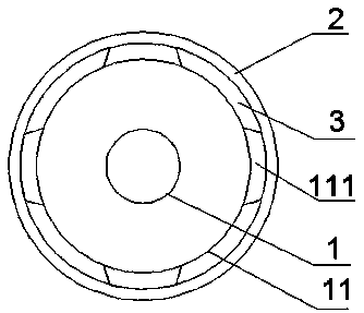
[0019] like figure 1 Shown: a permanent magnet motor heat dissipation structure, including a motor body 1, the motor body 1 is arranged in an inner cavity of a casing 2; the motor body 1 includes a casing 11 and a stator and a casing arranged in the casing Rotor; the casing 11 is provided with a plurality of protrusions 111 , so that a cooling channel 3 is formed between the casing 2 and the casing 11 of the motor body 1 .

[0020] The above technical solution has the following advantages: by setting the protrusion 111, on the one hand, when the motor body is installed in the inner cavity of a housing, a gap will be formed, that is, a heat dissipation channel will be formed, so that the heat emitted by the motor body can pass through the heat dissipation channel Dissipate, greatly improve the heat dissipation effect, and will not cau...


PUM


Abstract

The invention discloses a heat dissipation structure of a permanent magnet motor, which comprises a motor body, wherein the motor body is disposed in an inner cavity of a shell; the motor body comprises a casing, a stator and a rotor, and the stator and the rotor are disposed in the casing; and the casing is provided with a plurality of bulges so as to form a heat dissipation channel between the shell and the casing of the motor body. On the one hand, the structure is simple; and on the other hand, the heat dissipation effect is greatly improved without changing the volume of the original casing.

Description

technical field [0001] The invention relates to the technical field of motors, in particular to a heat dissipation structure of a permanent magnet motor. Background technique [0002] Permanent magnet motors generate a lot of heat during operation, which needs to be dissipated in time to avoid damage to surrounding components. Some motors are placed in the outside world, and the casing of the motor is usually a metal shell, and the heat generated by the motor will be dissipated through the casing of the motor; while some motors need to be placed in the cavity of some equipment, and if Placed in the cavity, and if the space of the cavity is small, when the motor and the cavity are fitted and installed, the gap between the motor and the cavity will be small, resulting in the failure of the motor shell to dissipate heat in time, resulting in poor heat dissipation. [0003] At present, in order to improve the heat dissipation of the motor, an additional heat sink or heat pipe i...

Claims


Application Information

Patent Timeline
Patent Type & Authority Applications(China)
IPC IPC(8): H02K5/20
CPCH02K5/20
Inventor 王旨杰周琪华
Owner 衡阳韵翔电机有限公司
Learn More